56-424-001 Spectrum Control, 56-424-001 Datasheet - Page 44
56-424-001
Manufacturer Part Number
56-424-001
Description
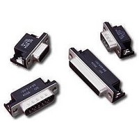
D-Subminiature Connectors 25 PIN FEMALE
Manufacturer
Spectrum Control
Type
Filtered D-Subr
Datasheet
1.56-424-001.pdf
(104 pages)
Specifications of 56-424-001
Number Of Contacts
25POS
Number Of Terminals
25
Plug / Receptacle
SKT
Contact Plating
Gold Over Nickel
Contact Pitch (mm)
2.76mm
Body Orientation
Right Angle
Mounting Style
Through Hole
Number Of Ports
1Port
Number Of Contact Rows
2
Operating Temp Range
-40C to 105C
Termination Method
Solder
Current Rating
5A
Housing Material
Steel
Contact Material
Phosphor Bronze
Product Length (mm)
53.04mm
Product Depth (mm)
19.2mm
Product Height (mm)
12.55mm
Product
Filtered Hoods & Connectors
Number Of Positions / Contacts
25
Shell Plating
Tin
Gender
Female
Mounting Angle
Right
Termination Style
Solder Pin
Operating Temperature Range
- 40 C to + 105 C
Lead Free Status / RoHS Status
Not Compliant
Available stocks
Company
Part Number
Manufacturer
Quantity
Price
Company:

Part Number:
56-424-001
Manufacturer:
API Technologies Corp
Quantity:
457


171
F - RoHS compliant version
D-Subminiature
Part Numbering System
Ordering Information
Example:
Filtered
D-Subminiature
Connectors
SPECTRUM CONTROL INC. • 8031 Avonia Rd. • Fairview, PA 16415 • Phone: 814-474-2207 • Fax: 814-474-2208 • Web site: www.spectrumcontrol.com
SPECTRUM CONTROL GmbH • Hansastrasse 6 • 91126 Schwabach, Germany • Phone: (49)-9122-795-0 • Fax: (49)-9122-795-58
To assist your efforts in selecting the correct Filtered Connector to meet your needs,
we have developed a part numbering system. All of the standard products are shown
in their respective catalog pages.
in a socket to straight PCB mount configuration. All connector positions have
a capacitance value of 840 pF and there are 4-40 threads on mounting flange.
- Standard connector
56 -
Part number 56-513-012-TI represents a Series 500 connector with 15 contacts
Product
Series
1 = Series 100
4 = Series F
5 = Series 500
6 = Series 600
7 = Series 700
C.O.B.
Ferrite
Low Profile
Hi-Density
High
Performance
56-513-012-TI
5 1 3 - 0 12
Contact Type/Termination
1 = Pin to solder cup
2 = Pin to 90° PCB mount
3 = Socket to straight PCB mount
4 = Socket to 90° PCB mount
5 = Pin-socket adapter
6 = Socket to solder cup
7 = Pin to straight PCB mount
Styles available for:
Series 400 only 2, 3, 4, 7
Series 100 1 thru 7
Series 500 only 2, 3, 4 & 7
Series 600 only 1, 2, 3, 4, 5
Series 700 1 thru 6
Note: 1 can be Pin to solder cup
or Pin to PCB for Series 700.
See charts pages 151-170.
Shell Size
Series 400,
Series 100 & 500
Series 600
Hi-Density
Series 700
0 = 9 Contacts
1 = 15 Contacts
2 = 25 Contacts
3 = 37 Contacts
0 = 15 Contacts
1 = 26 Contacts
2 = 44 Contacts
3 = 62 Contacts
4 = 78 Contacts
0 = 9 Contacts
1 = 15 Contacts
2 = 25 Contacts
3 = 37 Contacts
4 = 50 Contacts
-
TI
Line
Filtering
0 = All
9 = Special
positions
same
loading
(Series
600 only)
Capacitance
Value
Series 400
Series 100
Series 500
Series 600
Series 700
01 = Always
02 = 100 pF
03 = 220 pF
04 = 470 pF
05 = 820 pF
06 = 1500 pF
07 = 5600 pF
08 = 50 pF
09 = 180 pF
10 = 1000 pF
11 = 2200 pF
12 = 47 nF
10 = 120 pF
11 = 440 pF
12 = 840 pF
13 = 1000 pF
14 = 1500 pF
15 = 85 pF FT
16 = 180 pF FT
18 = 1000 pF FT
19 = 4000 pF FT
20 = Insulated
See filter specifi-
cation chart on
page 149 and
select part numbers
from Series 700
charts pages
151-170.
contact
Options
See options descriptions
on page 172
add suffix ending
Series 100
Series F
Series 500
Series 600 Hi-Density
Series 700
For option combinations, consult factory.
GBLF = Grounded board lock
GBL6 = for .062" boards (straight
GBL9 = for .093" boards (straight
GBL6 - for .062" boards (1.57mm)
GBL = Grounded board lock
GBL = Ground board lock
GBL = Grounded board lock
50G = 50 µ (1.27 µm) gold
50G = 50 µ (1.27 µm) gold plating
LIM = Metric M3.0 self-locking threads
MIB - M3 thread on rear of flange
TIB - 4-40 thread on rear of flange
GB = Metal bracket provides ground
3G - 30µ" gold (.76um)
5G - 50µ" gold (1.27um)
TIF - 4-40 thread on front of flange
GB - no board locks
HD =Hi-Density
GL - includes grounding board lock
GF - GL and jack screws
JS = Jackscrew mounting
JS - Jack screws
TI = 4-40 threads on mounting
LI = 4-40 UNC inserts
LI = 4-40 UNC inserts
M - M3 thread
S = Solder dipped tails
S = Solder dipped tails
_ - .120 thru-hole and 15µ" gold (.38um)
T - 4-40 threads
_ - No GBL attached
J - jack screws
SC and Straight PCBs
Right Angles and Adapters
and 4-40 threads
(15 socket only)
flange (.125" hole if not
selected)
includes 4-40 threads
(available only on 90° PCB)
and ferrite slab
provides enhanced LC
performance. (Available
only on 90° PCB)
connection, includes 4-40
self-locking threads (for right angle
mount only)
(right angle)
PCB mount) (1.57mm)
PCB mount (2.36mm)
Related parts for 56-424-001
Image
Part Number
Description
Manufacturer
Datasheet
Request
R


Part Number:
Description:
USB CONNECTOR, RECEPTACLE, 4POS, THD
Manufacturer:
Spectrum Control
Datasheet:
Part Number:
Description:
USB CONNECTOR, RECEPTACLE, 4POS, THD
Manufacturer:
Spectrum Control
Datasheet:
Part Number:
Description:
USB CONNECTOR, RECEPTACLE, 4POS, THD
Manufacturer:
Spectrum Control
Datasheet:

Part Number:
Description:
Rotary Switch,STRAIGHT,Number Of Positions:3,PC TAIL Terminal,ROTARY SHAFT,PCB Hole Count:12
Manufacturer:
Grayhill Inc
Datasheet:

Part Number:
Description:
Power Line Filters Single Stage
Manufacturer:
Spectrum Control Inc.
Datasheet:
Part Number:
Description:
High Current Single Line Feed-thru Filters
Manufacturer:
Spectrum Control Inc.
Datasheet:
Part Number:
Description:
Switched And Fused Filtered Power Entry Modules
Manufacturer:
Spectrum Control Inc.
Datasheet:
Part Number:
Description:
Surface Mount Emi Filters
Manufacturer:
Spectrum Control Inc.
Datasheet:

Part Number:
Description:
(PSMx Series) Surface Mount EMI Filters
Manufacturer:
Spectrum Control
Datasheet: