583616-5 TE Connectivity, 583616-5 Datasheet - Page 88
583616-5
Manufacturer Part Number
583616-5
Description
Manufacturer
TE Connectivity
Type
Bifurcated Contactr
Datasheet
1.583616-5.pdf
(96 pages)
Specifications of 583616-5
Number Of Contacts
1POS
Number Of Contact Rows
Not Required
Body Orientation
Straight
Contact Plating
Gold Over Nickel
Contact Material
Phosphor Bronze
Termination Method
Crimp
Mounting Style
Cable
Operating Temp Range
-55C to 105C
Pitch (mm)
Not Requiredmm
Housing Material
Not Required
Housing Color
Not Required
Current Rating (max)
5A
Contact Resistance Max
10
Product Type
Contact
Termination Method To Wire/cable
Crimp
Wire Insulation Diameter (mm [in])
0.89 – 1.40 [0.035 – 0.055]
Color Code
Orange
Contact Retention In Housing
Crimp Snap-In
Solder Tail Contact Plating
Nickel (30)
Centerline (mm [in])
2.54 [0.100], 3.18 [0.125], 3.96 [0.156]
Wire Range (mm [awg])
0.08-0.24² [28-24]
Contact Configuration
Bifurcated
Contact Plating, Mating Area, Material
Gold (15)
Contact Base Material
Phosphor Bronze
Rohs/elv Compliance
Not ELV/RoHS compliant
Lead Free Solder Processes
Not relevant for lead free process
Contact Packaging Method
Loose Piece
Lead Free Status / RoHS Status
Not Compliant


88
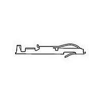
ACTION PIN Contacts with Wiping Feature,
.100 [2.54] Centerline
Material and Finish:
Copper alloy 725, plated .000015
[0.00038] gold per MIL-G-45204 in
contact area; .000001 [0.00003] min.
gold flash per MIL-G-45204 on post
with entire contact underplated .000050
[0.00127] nickel per QQ-N-290
Contact Combs
*At least two (2) contact combs required per housing.
Note: Other sizes can be made available, consult Tyco Electronics.
Reeled Contacts
Note: Other plating combinations and thicknesses can be made available,
Catalog 1654080
Issued 7-03
www.tycoelectronics.com
[37.72]
Per Comb*
Number of
1.485
Contacts
consult Tyco Electronics.
55
Post Area
[18.92]
[18.80]
.745
.740
[2.54]
.100
Number of
Contacts
Per Reel
35,000
(Comb)
Dimensions are in inches and
millimeters unless otherwise
specified. Values in brackets
are metric equivalents.
A
Dimension
137.16
5.400
A
Technical Documents:
(pages 186, 187):
Instruction Sheet 408-2665
Related Product Data:
Performance Specifications—
page 83
ACTION PIN Contact Description
and Application Specification—
page 94
Tooling—page 95
Card Edge Connectors
(Solder Type, Board-to-Board)
Linear ZIF Connectors, .100 x .100 [2.54 x 2.54] Centerline
Contact Area
[1.14]
.045
[0.64]
.025
119196-6
Number
Part
[15.24]
.600
Sq.
Ref.
Dimensions are shown for
reference purposes only.
Specifications subject
to change.
4-119311-1
Number
at Assembly
at Assembly
Prenotched
for Breakoff
for Breakoff
Part
Prenotched
[3.05]
.120
Recommended PC Board Hole Layout and Edge Pattern,
.100 [2.54] Centerline
Mother Board Hole Layout
*For ACTION PIN post hole diameter, see page 94.
Daughter Board Edge Pattern
Connector
Connector
Dia.
Lever
Lever
Style
Style
Min.
B
USA: 1-800-522-6752
Canada: 1-905-470-4425
Mexico: 01-800-733-8926
C. America: 52-55-5-729-0425
B
Max.
A
[2.49]
.098
.100
2.54
C L
C L
Entry
Style
Side
[2.54]
Top
.100
Typ.
[2.54 (No. of Pos. –1) +4.98]
[5.08]
.200
.100 (No. of Pos. –1) +.196
.100
2.54
Min.
A
South America: 55-11-3611-1514
Hong Kong: 852-2735-1628
Japan: 81-44-844-8013
UK: 44-141-810-8967
Dimensions
.240
6.10
.240
6.10
A
[1.19]
(Solder Post Only)*
.047
(Continued)
[1.78]
Dimensions
.206
5.23
.070
Dia. Typ.
B
C
.175
4.45
.320
8.13
—
C
B
Related parts for 583616-5
Image
Part Number
Description
Manufacturer
Datasheet
Request
R

Part Number:
Description:
Manufacturer:
TE Connectivity
Datasheet:

Part Number:
Description:
TWIN LEAF TERM.
Manufacturer:
TE Connectivity
Datasheet:
Part Number:
Description:
CONT.CRP.SNAP TW.LF. STRIP
Manufacturer:
TE Connectivity
Datasheet:

Part Number:
Description:
Printers THERMAL PRINTER HS-SLEEVE MARKER
Manufacturer:
TE Connectivity

Part Number:
Description:
High Speed / Modular Connectors 30P HEADER ASSY
Manufacturer:
TE Connectivity
Datasheet:

Part Number:
Description:
High Speed / Modular Connectors REC 6X005P R/A LT B-PLANE HS3
Manufacturer:
TE Connectivity
Datasheet:

Part Number:
Description:
High Speed / Modular Connectors 2MM HM RCPT 50P R/A AU
Manufacturer:
TE Connectivity
Datasheet:

Part Number:
Description:
High Speed / Modular Connectors 2MM HM RCPT 50P R/A AU
Manufacturer:
TE Connectivity
Datasheet:


Part Number:
Description:
Manufacturer:
TE Connectivity
Datasheet:


Part Number:
Description:
Manufacturer:
TE Connectivity
Datasheet:

Part Number:
Description:
Manufacturer:
TE Connectivity
Datasheet:

Part Number:
Description:
Manufacturer:
TE Connectivity
Datasheet: