583616-5 TE Connectivity, 583616-5 Datasheet - Page 61
583616-5
Manufacturer Part Number
583616-5
Description
Manufacturer
TE Connectivity
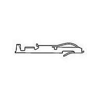
Type
Bifurcated Contactr
Datasheet
1.583616-5.pdf
(96 pages)
Specifications of 583616-5
Number Of Contacts
1POS
Number Of Contact Rows
Not Required
Body Orientation
Straight
Contact Plating
Gold Over Nickel
Contact Material
Phosphor Bronze
Termination Method
Crimp
Mounting Style
Cable
Operating Temp Range
-55C to 105C
Pitch (mm)
Not Requiredmm
Housing Material
Not Required
Housing Color
Not Required
Current Rating (max)
5A
Contact Resistance Max
10
Product Type
Contact
Termination Method To Wire/cable
Crimp
Wire Insulation Diameter (mm [in])
0.89 – 1.40 [0.035 – 0.055]
Color Code
Orange
Contact Retention In Housing
Crimp Snap-In
Solder Tail Contact Plating
Nickel (30)
Centerline (mm [in])
2.54 [0.100], 3.18 [0.125], 3.96 [0.156]
Wire Range (mm [awg])
0.08-0.24² [28-24]
Contact Configuration
Bifurcated
Contact Plating, Mating Area, Material
Gold (15)
Contact Base Material
Phosphor Bronze
Rohs/elv Compliance
Not ELV/RoHS compliant
Lead Free Solder Processes
Not relevant for lead free process
Contact Packaging Method
Loose Piece
Lead Free Status / RoHS Status
Not Compliant


Catalog 1654080
Issued 7-03
www.tycoelectronics.com
[9.59]
Material and Finish:
Housing—Green, glass-filled
polyester
Contacts—Phosphor bronze, duplex
plated .000030 [0.00076] gold in con-
tact area; .000100 [0.00254] bright tin
on posts, with entire contact under-
plated .000030 [0.00076] nickel
Insert—Brass
Related Product Data:
Keying Plug—page 63
PC Board Hole Layouts—See below
PC Board Edge Pattern—page 63
Technical Documents:
(pages 186, 187):
Product Specification
108-9044
Instruction Sheet 408-7772
.378
Typ.
[7.49]
[4.19]
.295
.165
.200 [5.08] Row-to-Row Spacing
[3.25]
Post Length
(See Chart)
.128
[3.18]
Flow Solder Post
.125
PC Board Hole Layout
Dia.
Recommended
Ref.
[5.08]
.200
B
[3.96]
.156
Dimensions are in inches and
millimeters unless otherwise
specified. Values in brackets
are metric equivalents.
[1.32]
.052
Card Edge Connectors
(Solder Type, Board-to-Board)
Mounting Ear
with Insert
Low Profile Connectors, .156 [3.96] Centerline
Dia.
[2.54]
.100
[5.08]
Threaded Inserts
4-40 NC-2B
(2 per connector)
.200
[9.59]
.378
Typ.
Dimensions are shown for
reference purposes only.
Specifications subject
to change.
[4.19]
[7.49]
.295
.165
.140 [3.56] Row-to-Row Spacing
[3.25]
[3.18]
.128
.125
Post Length
(See Chart)
PC Board Hole Layout
Flow Solder Post
#1 Cavity Identification
Dia.
Recommended
Ref.
[3.96]
.156
B
[4.06]
.160
USA: 1-800-522-6752
Canada: 1-905-470-4425
Mexico: 01-800-733-8926
C. America: 52-55-5-729-0425
PCBoard Thickness—
.055-.070 [1.40-1.78]
[3.56]
.140
[1.32]
.052
Molded Characters (Upper and Lower Case
Letters Omitting Letters G, I, O &Q)
1
A
Dia.
[1.78]
.070
2
B
[3.56]
.140
[3.96]
[3.96]
.156
.156
C
3
E
D
A
B
Typ.
Typ.
D
4
[4.19]
[7.49]
.295
.165
E
5
.235 [5.97] Row-to-Row Spacing
6
F
South America: 55-11-3611-1514
Hong Kong: 852-2735-1628
Japan: 81-44-844-8013
UK: 44-141-810-8967
[3.18]
.125
Solder Eyelet Contact
[7.11]
.280
Ref.
Ref.
(2 Plcs.)
[3.25]
.128
Dia.
[3.81]
.150
[6.35]
.250
[7.62]
.300
[11.68]
.460
[5.97]
.235
C
Ref.
61
Related parts for 583616-5
Image
Part Number
Description
Manufacturer
Datasheet
Request
R

Part Number:
Description:
Manufacturer:
TE Connectivity
Datasheet:

Part Number:
Description:
TWIN LEAF TERM.
Manufacturer:
TE Connectivity
Datasheet:
Part Number:
Description:
CONT.CRP.SNAP TW.LF. STRIP
Manufacturer:
TE Connectivity
Datasheet:

Part Number:
Description:
Printers THERMAL PRINTER HS-SLEEVE MARKER
Manufacturer:
TE Connectivity

Part Number:
Description:
High Speed / Modular Connectors 30P HEADER ASSY
Manufacturer:
TE Connectivity
Datasheet:

Part Number:
Description:
High Speed / Modular Connectors REC 6X005P R/A LT B-PLANE HS3
Manufacturer:
TE Connectivity
Datasheet:

Part Number:
Description:
High Speed / Modular Connectors 2MM HM RCPT 50P R/A AU
Manufacturer:
TE Connectivity
Datasheet:

Part Number:
Description:
High Speed / Modular Connectors 2MM HM RCPT 50P R/A AU
Manufacturer:
TE Connectivity
Datasheet:


Part Number:
Description:
Manufacturer:
TE Connectivity
Datasheet:


Part Number:
Description:
Manufacturer:
TE Connectivity
Datasheet:

Part Number:
Description:
Manufacturer:
TE Connectivity
Datasheet:

Part Number:
Description:
Manufacturer:
TE Connectivity
Datasheet: