TFDU6103-TT3 Vishay, TFDU6103-TT3 Datasheet - Page 2
TFDU6103-TT3
Manufacturer Part Number
TFDU6103-TT3
Description
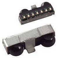
Infrared Transceivers SIR 115.2kbits Top View
Manufacturer
Vishay
Datasheet
1.TFDU6103-TR3.pdf
(13 pages)
Specifications of TFDU6103-TT3
Data Rate Max
4Mbps
Data Transmission Distance
1m
Peak Wavelength
886nm
Supply Current
2mA
Supply Voltage Range
2.4V To 5.5V
Operating Temperature Range
-25°C To +85°C
Msl
MSL 4 - 72 Hours
Data Rate
4Mbs (FIR)
Idle Current, Typ @ 25° C
2mA
Link Range, Low Power
1m
Operating Temperature
-25°C ~ 85°C
Orientation
Top View
Shutdown
*
Size
9.7mm x 4.7mm x 4mm
Standards
IrPHY 1.4
Supply Voltage
2.4 V ~ 5.5 V
Lead Free Status / RoHS Status
Lead free / RoHS Compliant
Lead Free Status / RoHS Status
Lead free / RoHS Compliant, Lead free / RoHS Compliant
Available stocks
Company
Part Number
Manufacturer
Quantity
Price


TFDU6103
Vishay Semiconductors
FUNCTIONAL BLOCK DIAGRAM
PINOUT
TFDU6103
weight 0.2 g
www.vishay.com
2
PIN DESCRIPTION
NUMBER
PIN
1
2
3
4
5
6
7
8
17087
IRED anode
SYMBOL
cathode
IRED
GND
V
RXD
V
TXD
SD
NC
CC2
CC1
”U” Option Baby Face (universal)
18468
1
IRED
irdasupportAM@vishay.com, irdasupportAP@vishay.com,
Shutdown, also used for dynamic mode switching. Setting this pin active places the module
into shutdown mode. On the falling edge of this signal, the state of the TXD pin is sampled
2
Received data output, push-pull CMOS driver output capable of driving a standard CMOS
Connect IRED anode directly to V
disables the LED driver if the TXD pin is asserted for longer than 100 µs. When used in
This input is used to transmit serial data when SD is low. An on-chip protection circuit
For technical questions within your region, please contact one of the following:
3
SD
TXD
4
conjunction with the SD pin, this pin is also used to set receiver speed mode
and used to set receiver low bandwidth (TXD = low, SIR) or high bandwidth
5
Floating with a weak pull-up of 500 k (typ.) in shutdown mode
or TTL load. No external pull-up or pull-down resistor is required.
6
might be necessary for reducing the internal power dissipation.
An unregulated separate power supply can be used at this pin
Fast Infrared Transceiver Module (FIR, 4 Mbit/s)
Detector
7
IRED cathode, internally connected to driver transistor
8
Am pl if ie r
(TXD = high, MIR and FIR) mode
for 2.4 V to 5.5 V Operation
CC2
DESCRIPTION
Supply voltage
. For voltages higher than 3.6 V an external resistor
Co mp ar ator
Lo gi c
and
Contro l
Ground
GND
Definitions:
In the Vishay transceiver datasheets the following
nomenclature is used for defining the IrDA operating modes:
SIR: 2.4 kbit/s to 115.2 kbit/s, equivalent to the basic serial
infrared standard with the physical layer version IrPhy 1.0
MIR: 576 kbit/s to 1152 kbit/s
FIR: 4 Mbit/s
VFIR: 16 Mbit/s
MIR and FIR were implemented with IrPhy 1.1, followed by
IrPhy 1.2, adding the SIR low power standard. IrPhy 1.3
extended the low power option to MIR and FIR and VFIR was
added with IrPhy 1.4. A new version of the standard in any
case obsoletes the former version.
Note
We apologize to use sometimes in our documentation the
abbreviation LED and the word light emitting diode instead of
infrared emitting diode (IRED) for IR-emitters. That is by definition
wrong; we are here following just a bad trend.
Typical values are for design aid only, not guaranteed nor subject to
production testing and may vary with time.
V
CC1
irdasupportEU@vishay.com
Contro lle d
Dr iv er
Tr i- Stat e
Dr iv er
IR ED C
V
RXD
CC2
Document Number: 81211
Rev. 1.4, 29-Jul-09
I/O
O
I
I
ACTIVE
High
High
Low
Related parts for TFDU6103-TT3
Image
Part Number
Description
Manufacturer
Datasheet
Request
R

Part Number:
Description:
Manufacturer:
Vishay Semiconductors
Datasheet:

Part Number:
Description:
Infrared Transceivers SIR 115.2kbits Side View
Manufacturer:
Vishay
Datasheet:

Part Number:
Description:
357-036-542-201 CARDEDGE 36POS DL .156 BLK LOPRO
Manufacturer:
Vishay
Datasheet:
Part Number:
Description:
357-036-542-201 CARDEDGE 36POS DL .156 BLK LOPRO
Manufacturer:
Vishay
Datasheet:
Part Number:
Description:
357-036-542-201 CARDEDGE 36POS DL .156 BLK LOPRO
Manufacturer:
Vishay
Datasheet:
Part Number:
Description:
357-036-542-201 CARDEDGE 36POS DL .156 BLK LOPRO
Manufacturer:
Vishay
Datasheet:
Part Number:
Description:
357-036-542-201 CARDEDGE 36POS DL .156 BLK LOPRO
Manufacturer:
Vishay
Datasheet:
Part Number:
Description:
357-036-542-201 CARDEDGE 36POS DL .156 BLK LOPRO
Manufacturer:
Vishay
Datasheet:
Part Number:
Description:
357-036-542-201 CARDEDGE 36POS DL .156 BLK LOPRO
Manufacturer:
Vishay
Datasheet:
Part Number:
Description:
357-036-542-201 CARDEDGE 36POS DL .156 BLK LOPRO
Manufacturer:
Vishay
Datasheet:
Part Number:
Description:
357-036-542-201 CARDEDGE 36POS DL .156 BLK LOPRO
Manufacturer:
Vishay
Datasheet:
Part Number:
Description:
357-036-542-201 CARDEDGE 36POS DL .156 BLK LOPRO
Manufacturer:
Vishay
Datasheet:
Part Number:
Description:
357-036-542-201 CARDEDGE 36POS DL .156 BLK LOPRO
Manufacturer:
Vishay
Datasheet:
Part Number:
Description:
357-036-542-201 CARDEDGE 36POS DL .156 BLK LOPRO
Manufacturer:
Vishay
Datasheet:
Part Number:
Description:
357-036-542-201 CARDEDGE 36POS DL .156 BLK LOPRO
Manufacturer:
Vishay
Datasheet: