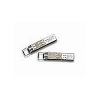
AFBR-57R5AP Avago Technologies US Inc., AFBR-57R5AP Datasheet

AFBR-57R5AP
Specifications of AFBR-57R5AP
Available stocks
Related parts for AFBR-57R5AP
AFBR-57R5AP Summary of contents
Page 1
... AFBR-57R5AP Digital Diagnostic SFP, 850 nm, 4.25/2.125/1.0625 GBd Optical Transceiver Data Sheet 850 nm, SFP (Small Form Pluggable), Low Voltage (3.3 V) Digital Diagnostic Optical Transceiver Description Applications • Fibre channel systems – Director class switches – Fabric switches – HBA cards • Disk and tape drive arrays Related Products • ...
Page 2
Description, continued Installation Digital Diagnostic Interface and Serial Identification 2 Predictive Failure Identification Compliance Prediction Fault Isolation Component Monitoring ...
Page 3
OPTICAL INTERFACE RECEIVER LIGHT FROM FIBER TRANSMITTER LIGHT TO FIBER Figure 1. Transceiver functional diagram. Transmitter Section Transmit Disable (Tx_Disable) 3 AMPLIFICATION PHOTO-DETECTOR & QUANTIZATION CONTROLLER & MEMORY LASER DRIVER & VCSEL SAFETY CIRCUITRY Transmit Fault (Tx_Fault) ELECTRICAL INTERFACE RD+ ...
Page 4
Receiver Section Receiver Loss of Signal (Rx_LOS) Functional Data I/O 4 Application Support Caution Ordering Information www.Avago.com www.sffcommittee.org ...
Page 5
Regulatory Compliance Electrostatic Discharge (ESD) Table 1. Regulatory Compliance Feature Electrostatic Discharge (ESD) to the Electrical Pins Electrostatic Discharge (ESD) to the Duplex LC Receptacle Electrostatic Discharge (ESD) to the Optical Connector Electromagnetic Interference (EMI) Immunity Laser Eye Safety and ...
Page 6
Tx_DISABLE Tx_FAULT SERDES IC PROTOCOL IC LOSS OF SIGNAL 4 MODULE DETECT SCL SDA Figure 2. Typical application configuration 0 0 SFP MODULE HOST BOARD NOTE: ...
Page 7
Table 2. Pin Description Pin Name Function/Description 1 VeeT Transmitter Ground 2 TX_FAULT Transmitter Fault Indication – High indicates a fault condition 3 TX_DISABLE Transmitter Disable – Module electrical input disables on high or open 4 MOD-DEF2 Module Definition 2 ...
Page 8
Table 3. Absolute Maximum Ratings Parameter Storage Temperature Case Operating Temperature Relative Humidity Supply Voltage Low Speed Input Voltage Notes; 1. Absolute Maximum Ratings are those values beyond which damage to the device may occur if these limits are exceeded ...
Page 9
Table 6. Transmitter and Receiver Electrical Characteristics ( VccT, VccR = 3.3 V 10%) C Parameter High Speed Data Input: Transmitter Differential Input Voltage (TD +/-) High Speed Data Output: Receiver Differential Output Voltage ...
Page 10
Table 7. Transmitter Optical Characteristics ( VccT, VccR = 3.3V 10%) C Parameter Modulated Optical Output Power (OMA) (Peak-to-Peak) 4.25 Gb/s Modulated Optical Output Power (OMA) (Peak-to-Peak) 2.125 Gb/s Modulated Optical Output Power (OMA) ...
Page 11
Table 8. Receiver Optical Characteristics ( VccT, VccR = 3.3 V 10%) C Parameter Input Optical Power [Overdrive] Input Optical Modulation Amplitude (Peak-to-Peak) 4.25 Gb/s [Sensitivity] Input Optical Modulation Amplitude (Peak-to-Peak) 2.125 Gb/s [Sensitivity] ...
Page 12
Table 9. Transceiver SOFT DIAGNOSTIC Timing Characteristics ( VccT, VccR = 3.3 V 10%) C Parameter Hardware TX_DISABLE Assert Time Hardware TX_DISABLE Negate Time Time to initialize, including reset of TX_FAULT Hardware TX_FAULT Assert ...
Page 13
Table 10. Transceiver Digital Diagnostic Monitor (Real Time Sense) Characteristics ( VccT, VccR = 3.3 V 10%) C Parameter Transceiver Internal Temperature Accuracy Transceiver Internal Supply Voltage Accuracy Transmitter Laser DC Bias Current Accuracy ...
Page 14
... Addresses 63 and 95 are checksums calculated (per SFF-8472 and SFF-8074) and stored prior to product shipment. 7. Addresses 68-83 specify the AFBR-57R5AP ASCII serial number and will vary on a per unit basis. 8. Addresses 84-91 specify the AFBR-57R5AP ASCII date code and will vary on a per date code basis. 14 ...
Page 15
... Transmitted average optical power (Tx Pwr) is decoded bit unsigned integer in increments of 0 Received average optical power (Rx Pwr) is decoded bit unsigned integer in increments of 0 Bytes 56-94 are not intended for use with AFBR-57R5AP, but have been set to default values per SFF-8472. 7. Byte checksum calculated (per SFF-8472) and stored prior to product shipment. ...
Page 16
... Indicates transceiver is powered and real time sense data is ready Ready) Notes: 1. The response time for soft commands of the AFBR-57R5AP is 100 msec as specified by the MSA SFF-8472. 2. Bit 6 is logic OR’d with the SFP TX_DISABLE input pin 3 ... either asserted will disable the SFP transmitter. ...
Page 17
... DEVICE SHOWN WITH DUST CAP AND BAIL DELATCH 6.25 0.05 TX Figure 5. Module drawing. 17 13.6 1.91 12.4 0.2 RX +0.2 13.6 0 55.3 0.2 Agilent AFBR-57R5AP 650nm LASER PROD 21CRF(J) CLASS1 SINGAPORE 0445 13.4 PPOG-4402-Din2 SN: A30445CD1C 0.81 UNCOMPRESSED 8.5 0.65 UNCOMPRESSED 14.9 UNCOMPRESSED 0.1 0.1 ...
Page 18
X Y 16.25 MIN. PITCH B PCB EDGE 5.68 8.58 11.08 16.25 REF. 14.25 2.0 11x 3 3.2 PIN 1 10.93 9.6 0.8 TYP 1.55 0.05 0 DETAIL 1 Figure 6. SFP ...
Page 19
MAX. 11.73 REF 9.8 MAX. PCB Figure 7. SFP Assembly drawing. 19 Tcase REFERENCE POINT 15.25 0.1 10 REF 10.4 (to PCB) 0.4 0.1 16.25 0.1 MIN. PITCH (below PCB) DIMENSIONS ARE IN ...
Page 20
Customer Manufacturing Processes This module is pluggable and is not designed for aqueous wash, IR reflow, or wave soldering processes. For product information and a complete list of distributors, please go to our website: Avago, Avago Technologies, and the A ...


