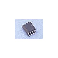
HV825MG Supertex, HV825MG Datasheet - Page 3

HV825MG
Manufacturer Part Number
HV825MG
Description
Display Drivers HVCMOS
Manufacturer
Supertex
Datasheet
1.HV825LG-G.pdf
(5 pages)
Specifications of HV825MG
Driver Type
EL Lamp Drivers
Maximum Operating Temperature
+ 85 C
Mounting Style
SMD/SMT
Package / Case
MSOP-8
Minimum Operating Temperature
- 25 C
Lead Free Status / RoHS Status
Lead free / RoHS Compliant
Available stocks
Company
Part Number
Manufacturer
Quantity
Price
Part Number:
HV825MG
Manufacturer:
SUPERTEX
Quantity:
20 000
Test Circuit
For additional information, see Application Notes AN-H33 and AN-H34.
External Component Description
Typical Performance
Notes:
External
Component
Diode
C
R
Resistor
R
Resistor
L
C
Capacitor
X
1.
S
EL-Osc
SW-Osc
SW
Inductor
Lamp Size
Capacitor
V
Murata part # LQH4N561K04 (Max DC resistance = 14.5Ω)
1.5in
DD
= V
IN
2
= 1.0V - 1.6V
OFF = GND
ON = V
Fast reverse recovery, 1N4148 or equivalent.
0.01 to 0.1µF, 100V capacitor to GND is used to store the energy transferred from the inductor.
The lamp frequency is controlled via the R
As the lamp frequency increases, the amount of current drawn from the battery will increase and the
output voltage V
at higher frequencies.
In general, as the lamp size increases, a larger R
the color of the lamp is dependent upon its frequency and the shade of the color will change slightly with
different frequencies.
The switching frequency of the inductor is controlled via the R
as the R
battery will decrease and the output voltage V
The inductor L
is being charged. When the internal switch is off, the charge in the inductor will be transferred to the
high voltage capacitor C
therefore to the lamp. In general smaller value inductors, which can handle more current, are more suit-
able to drive larger size lamps. As the inductor value decreases, the switching frequency of the inductor
(controlled by R
The test circuit uses a Murata (LQH4N561) 560µH inductor. Using different inductor values or inductors
from different manufacturers will affect the performance.
As the inductor value decreases, smaller R
An inductor with the same inductance value, (560µH), but lower series resistance, will charge faster.
The R
sumption.
A 1nF capacitor is recommended from the RSW-Osc pin to GND. This capacitor is used to shunt any
switching noise that may couple into the RSW-Osc pin. A C
Selection Guide Line
DD
SW-Osc
Enable
SW-Osc
1.5V
V
0.1µF
resistor value needs to be decreased to prevent inductor saturation and high current con-
560µH
IN
decreases. As the switching frequency increases, the amount of current drawn from the
X
SW-Osc
CS
is used to boost up the low input voltage. When the internal switch is on, the inductor
1
will decrease. This is because the lamp will draw more current from V
1N4148
) should be increased to avoid saturation.
0.01µF
100V
S
750KΩ
. The energy stored in the capacitor is connected to the internal H-bridge and
30mA
I
DD
C
1nF
SW
1
2
3
4
VDD
RSW-Osc
CS
LX
HV825
1.0MΩ
SW-Osc
EL-Osc
3
REL-Osc
CS
values should be used. This will prevent inductor saturation.
GND
. The lamp frequency increases as the R
VA
VB
will also decrease.
EL-Osc
7
8
6
5
56V
V
CS
is recommended to provide higher V
SW
2.2KΩ
SW-Osc
larger than 1.0nF is not recommended.
Equivalent to
1.5in
. The switching frequency increases
2
lamp
450Hz
4.7nF
f
EL
EL-Osc
Brightness
CS
3.65ft-lm
CS
when driven
decreases.
. However,
HV825


