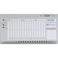
490NAD91103 SQUARE D, 490NAD91103 Datasheet - Page 13

490NAD91103
Manufacturer Part Number
490NAD91103
Description
PROFIBUS PLC CONNECTOR, PLUG, 9POS
Manufacturer
SQUARE D
Series
NADr
Datasheet
1.490NAD91103.pdf
(60 pages)
Specifications of 490NAD91103
Connector Type
Programmable Logic Controller
Gender
Plug
No. Of Contacts
9
Connector Mounting
Cable
For Use With
Square D Altivar 71 Profibus DP Drives
Lead Free Status / RoHS Status
Lead free / RoHS Compliant
1
09/2004
Characteristics of Thermal Overload Pre-alarm Function Module LUFW10
Activation threshold
Hysteresis between activation and switching off
Display
Supply
Digital output characteristics
Characteristics of Motor Load Indication Function Module LUFV2
Analog output
Signal delivered
Load impedance
Signal characteristics with advanced control unit
Signal characteristics with
multifunction control unit
Supply
Characteristics of AS-i Communication Module ASILUFC5
Approval
AS-i profile
Ambient air temperature
AS-i supply
Current consumption
Auxiliary supply
Current consumption
Number of outputs
Switching capacity of the solid state outputs
Indication/diagnostics
Characteristics of Modbus
Physical interface
Connector
Protocol
Maximum transmission speed
Maximum return time
Addressing (Modbus drop numbers)
Ambient air temperature
Supply for the outputs
Current consumption
Number of outputs
Switching capacity of the solid state outputs
Indication/diagnostics
Connection Characteristics of Function and Communication Modules
Module type
Connectors
Flexible cable without cable end
Flexible cable
with cable end
Solid cable without cable end
AWG conductor size (one or two conductors)
Tightening torque
Slotted screwdriver
Use a double cable end.
Without insulated
ferrule
With insulated
ferrule
By the AS-i system
On 24 V supply for the outputs
On 24 V supply for the outputs
®
Communication Module LULC031
Pitch
1 conductor
2 identical conductors
1 conductor
2 identical conductors
1 conductor
2 identical conductors
1 conductor
2 identical conductors
Type
AC-15
DC-13
Minimum
Maximum
Typical
Accuracy
Accuracy
Resolution
1
LUFW10
5.08 mm
0.2–1.5 mm²
0.2–1 mm²
0.25–1.5 mm²
0.25–1 mm²
0.25–1.5 mm²
0.5–1.5 mm²
0.2–1.5 mm²
0.2–1 mm²
12–24 AWG
5 lb-in
(0.5–0.6 N•m)
1/8 in
Fixed at 88% of the thermal tripping state
5 %
By LED on front panel
Powered by the control unit
N.O. contact
230 V max; 400 VA 100,000 operating cycles
24 V; 50 W 100,000 operating cycles
4–20 mA
Value of I average/Ir ratio within the range of 0 to 2
–
500 Ω
100 Ω
± 6 %
± 10 %
1 % of Ir
External 24 Vdc
AS-i V2.1 no. (pending)
7.D.F.0
Operation -13 to + 158 °F (- 25 to + 70 °C)
29.5–31.5 V
Normal operation: 25 mA
Fault condition: 30 mA
24 Vdc ± 30 %
200 mA
2 dedicated to power base coil operation
0.5 A/24 V (outputs protected against short-circuits)
By 2 LEDs on front panel
RS-485 multi-drop
RJ45 on front panel
Modbus RTU
19,200 bit/s (self-configuration up to this value)
30 ms (from LULC031 to PLC and back to LULC031)
By switches: from 0–31
Operation -13 to +131 °F (- 25 to +55 °C)
24 Vdc
200 mA
3, of which 2 are dedicated to power base coil operation
0.5 A/24 V
LUFV2
3.81 mm
0.14–1 mm²
0.14–0.75 mm²
0.25–1 mm²
0.25–0.34 mm²
0.25–0.5 mm²
0.5 mm²
0.14–1 mm²
0.14–0.5 mm²
16–28 AWG
2 lb-in
(0.22–0.25 N•m)
3/32 in
ASILUFC5
Inputs and
24 V auxiliary
5.08 mm
0.2–1.5 mm²
0.2–1 mm²
0.25–1.5 mm²
0.25–1 mm²
0.25–1.5 mm²
0.5–1.5 mm²
0.2–1.5 mm²
0.2–1 mm²
12–24 AWG
5 lb-in
(0.5–0.6 N•m)
1/8 in
© 2004 Schneider Electric All Rights Reserved
TeSys® U-Line Motor Starters
Outputs
3.81 mm
0.14–1 mm²
0.14–0.75 mm²
0.25–1 mm²
0.25–0.34 mm²
0.25–0.5 mm²
0.5 mm²
0.14–1 mm²
0.14–0.5 mm²
16–28 AWG
2 lb-in
(0.22–0.25 N•m)
3/32 in
LULC031
3.81 mm
0.14–1 mm²
0.14–0.75 mm²
0.25–1 mm²
0.25–0.34 mm²
0.25–0.5 mm²
0.5 mm²
0.14–1 mm²
0.14–0.5 mm²
16–28 AWG
2 lb-in
(0.22–0.25 N•m)
3/32 in
Characteristics
LUFC00
3.81 mm
0.14–1 mm²
0.14–0.75 mm²
0.25–1 mm²
0.25–0.34 mm²
0.25–0.5 mm²
0.5 mm²
0.14–1 mm²
0.14–0.5 mm²
16–28 AWG
2 lb-in
(0.22–0.25 N•m)
1/8 in
13


