CDB3318 Cirrus Logic Inc, CDB3318 Datasheet - Page 36
CDB3318
Manufacturer Part Number
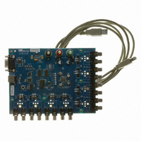
CDB3318
Description
Eval Bd - 8-channel Digital Vol Cntrl
Manufacturer
Cirrus Logic Inc
Specifications of CDB3318
Main Purpose
Audio, Volume Control
Embedded
No
Utilized Ic / Part
CS3318
Primary Attributes
8 Single-Ended Analog Inputs and Outputs, USB or RS232 Interface
Secondary Attributes
Graphical User Interface
Description/function
Audio DSPs
Operating Supply Voltage
8 V to 9 V
Product
Audio Modules
Lead Free Status / RoHS Status
Contains lead / RoHS non-compliant
For Use With/related Products
CS3310
Lead Free Status / RoHS Status
Contains lead / RoHS non-compliant, Contains lead / RoHS non-compliant
Other names
598-1497


36
7.8
7.8.1
7.9
7.10
7.10.1 Master 1 Volume Control (Bits 7:0)
M1_Ch8M
Reserved
M1_Vol7
7
7
7
Freeze Control - Address 0Fh
Master 1 Mask - Address 10h
Each bit in this register serves as a Master 1 mask for its corresponding channel.
If a mask bit is set to ‘1’, the corresponding channel is unmasked, meaning that it will be affected by the
Master 1 volume and muting controls.
If a mask bit is set to ‘0’, the corresponding channel is masked, meaning that it will not be affected by the
Master 1 volume and muting controls.
This register defaults to FFh (all channels unmasked).
Master 1 Volume - Address 11h
Freeze (Bit 7)
Default = 0
Function:
Default = 11010010
Function:
When the Freeze bit is set, the Freeze function allows modifications to the control port registers with-
out changes taking effect until Freeze bit is cleared. To make multiple changes in the Control Port
registers take effect simultaneously, set the Freeze bit, make all register changes, then clear the
Freeze bit.
The Master 1 volume control register allows the user to simultaneously gain or attenuate all un-
masked channels in 0.5 dB increments. The volume changes are implemented as dictated by the ZC-
Mode[1:0] and TimeOut[2:0] bits in the Device Config 2 register (see
Address 0Ch” on page
The value of the Master 1 volume control register is mapped to the desired 0.5 dB step Master 1 vol-
ume setting by the following equation:
In the equation above, “Desired Volume Setting in dB” is determined by rounding the desired ¼ dB
resolution volume setting down to ½ dB resolution.
It should be noted that input values outside the CS3318’s analog range of +22 dB to -96 dB are valid,
however, the volume of each channel will be limited to the CS3318’s analog range (see
its” on page
See
M1_Ch7M
Reserved
M1_Vol6
Table 5 on page 31
6
6
6
20).
M1_Ch6M
Reserved
M1_Vol5
Register Value
5
5
5
34).
for example register settings.
M1_Ch5M
Reserved
M1_Vol4
4
4
4
=
(
2
×
Desired Volume Setting in dB
M1_Ch4M
Reserved
M1_Vol3
3
3
3
M1_Ch3M
Reserved
M1_Vol2
2
2
2
)
“Device Configuration 2 -
+
M1_Ch2M
Reserved
M1_Vol1
210
1
1
1
“Volume Lim-
M1_Ch1M
CS3318
M1_Vol0
Freeze
DS693F1
0
0
0
Related parts for CDB3318
Image
Part Number
Description
Manufacturer
Datasheet
Request
R

Part Number:
Description:
Development Kit
Manufacturer:
Cirrus Logic Inc
Datasheet:
Part Number:
Description:
Development Kit
Manufacturer:
Cirrus Logic Inc
Datasheet:


Part Number:
Description:
High-efficiency PFC + Fluorescent Lamp Driver Reference Design
Manufacturer:
Cirrus Logic Inc
Datasheet:
Part Number:
Description:
Development Kit
Manufacturer:
Cirrus Logic Inc
Datasheet:
Part Number:
Description:
Development Kit
Manufacturer:
Cirrus Logic Inc
Datasheet:

Part Number:
Description:
Development Kit
Manufacturer:
Cirrus Logic Inc
Datasheet:
Part Number:
Description:
Development Kit
Manufacturer:
Cirrus Logic Inc
Datasheet:
Part Number:
Description:
Development Kit
Manufacturer:
Cirrus Logic Inc
Datasheet:
Part Number:
Description:
Development Kit
Manufacturer:
Cirrus Logic Inc
Datasheet:

Part Number:
Description:
EVALUATION BOARD FOR CS8427
Manufacturer:
Cirrus Logic Inc
Datasheet:

Part Number:
Description:
BOARD EVAL FOR CS8416 RCVR
Manufacturer:
Cirrus Logic Inc
Datasheet:

Part Number:
Description:
EVALUATION BOARD FOR CS8420
Manufacturer:
Cirrus Logic Inc
Datasheet:

Part Number:
Description:
KIT DEVELOPMENT EP9315 ARM9
Manufacturer:
Cirrus Logic Inc
Datasheet:

Part Number:
Description:
KIT DEVELOPMENT EP9302 ARM9
Manufacturer:
Cirrus Logic Inc
Datasheet: