CDB3318 Cirrus Logic Inc, CDB3318 Datasheet - Page 21
CDB3318
Manufacturer Part Number
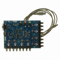
CDB3318
Description
Eval Bd - 8-channel Digital Vol Cntrl
Manufacturer
Cirrus Logic Inc
Specifications of CDB3318
Main Purpose
Audio, Volume Control
Embedded
No
Utilized Ic / Part
CS3318
Primary Attributes
8 Single-Ended Analog Inputs and Outputs, USB or RS232 Interface
Secondary Attributes
Graphical User Interface
Description/function
Audio DSPs
Operating Supply Voltage
8 V to 9 V
Product
Audio Modules
Lead Free Status / RoHS Status
Contains lead / RoHS non-compliant
For Use With/related Products
CS3310
Lead Free Status / RoHS Status
Contains lead / RoHS non-compliant, Contains lead / RoHS non-compliant
Other names
598-1497


DS693F1
5.6
5.6.1
5.6.2
5.6.3
Muting Controls
The CS3318 provides flexible muting capabilities to complement its comprehensive volume control abilities.
Each channel’s mute state may be controlled on an individual channel basis, by any of 3 master mute con-
trols, and by the hardware MUTE input pin.
The mute state of any channel within the CS3318 is determined by the logical OR of four conditions, and
the channel will mute if any one or more of the conditions are met. These conditions are:
1. The channel’s individual mute condition is set.
2. One or more of the channel’s unmasked master mute conditions are set.
3. The hardware mute input is enabled and active.
4. The channel’s effective volume (See
The CS3318 incorporates zero-crossing detection capabilities, and all muting changes are implemented as
dictated by the zero-crossing detection settings (see
Individual Channel Mute Controls
The CS3318 provides 8 individual channel mute controls. These controls can be used to individually mute
each of the input/output channels independent of all other volume and mute settings.
Individual channel mute control is accomplished by setting or clearing the channel’s corresponding
MuteChX bit in the Mute Control register.
Master Mute Controls
The CS3318 master mute controls allow the user to simultaneously control the mute state of all channels,
or a user-defined subset of all channels within a device. A total of 3 master mute controls, M1_Mute,
M2_Mute, and M3_Mute, are provided for comprehensive and flexible control.
Master mute control is accomplished by setting or clearing the MX_Mute bit in the corresponding Master
Control register. Each master mute control affects only those channels unmasked in its corresponding
Master X Mask register.
Hardware Mute Control
The CS3318 implements a hardware MUTE input pin to allow the user to control the mute state of all chan-
nels with an external level-active signal. By default, the MUTE input is configured for active low operation,
and all channels will be held in a mute state whenever this input is low.
For enhanced flexibility, setting the MutePolarity bit will configure the MUTE input pin for active high op-
eration. Additionally, the EnMuteIn bit may be cleared to disable the CS3318’s response to the MUTE in-
put signal.
Referenced Control
MuteChX .............................
Referenced Control
MX_Mute.............................
Master X Mask ....................
Referenced Control
MutePolarity ........................
EnMuteIn.............................
Register Location
Register Location
Register Location
“Mute Control - Address 0Ah” on page 33
“Master 1 Mute (Bit 1)” on page 37
“Master 2 Mute (Bit 1)” on page 38
“Master 3 Mute (Bit 1)” on page 39
“Master 1 Mask - Address 10h” on page 36
“Master 2 Mask - Address 13h” on page 37
“Master 3 Mask - Address 16h” on page 38
“MUTE Input Polarity (Bit 4)” on page 33
“Enable MUTE Input (Bit 5)” on page 33
Equation 1 on page
“Zero-Crossing Detection” on page
19) is less than -96 dB.
22).
CS3318
21
Related parts for CDB3318
Image
Part Number
Description
Manufacturer
Datasheet
Request
R

Part Number:
Description:
Development Kit
Manufacturer:
Cirrus Logic Inc
Datasheet:
Part Number:
Description:
Development Kit
Manufacturer:
Cirrus Logic Inc
Datasheet:


Part Number:
Description:
High-efficiency PFC + Fluorescent Lamp Driver Reference Design
Manufacturer:
Cirrus Logic Inc
Datasheet:
Part Number:
Description:
Development Kit
Manufacturer:
Cirrus Logic Inc
Datasheet:
Part Number:
Description:
Development Kit
Manufacturer:
Cirrus Logic Inc
Datasheet:

Part Number:
Description:
Development Kit
Manufacturer:
Cirrus Logic Inc
Datasheet:
Part Number:
Description:
Development Kit
Manufacturer:
Cirrus Logic Inc
Datasheet:
Part Number:
Description:
Development Kit
Manufacturer:
Cirrus Logic Inc
Datasheet:
Part Number:
Description:
Development Kit
Manufacturer:
Cirrus Logic Inc
Datasheet:

Part Number:
Description:
EVALUATION BOARD FOR CS8427
Manufacturer:
Cirrus Logic Inc
Datasheet:

Part Number:
Description:
BOARD EVAL FOR CS8416 RCVR
Manufacturer:
Cirrus Logic Inc
Datasheet:

Part Number:
Description:
EVALUATION BOARD FOR CS8420
Manufacturer:
Cirrus Logic Inc
Datasheet:

Part Number:
Description:
KIT DEVELOPMENT EP9315 ARM9
Manufacturer:
Cirrus Logic Inc
Datasheet:

Part Number:
Description:
KIT DEVELOPMENT EP9302 ARM9
Manufacturer:
Cirrus Logic Inc
Datasheet: