CDB3318 Cirrus Logic Inc, CDB3318 Datasheet - Page 23
CDB3318
Manufacturer Part Number
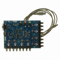
CDB3318
Description
Eval Bd - 8-channel Digital Vol Cntrl
Manufacturer
Cirrus Logic Inc
Specifications of CDB3318
Main Purpose
Audio, Volume Control
Embedded
No
Utilized Ic / Part
CS3318
Primary Attributes
8 Single-Ended Analog Inputs and Outputs, USB or RS232 Interface
Secondary Attributes
Graphical User Interface
Description/function
Audio DSPs
Operating Supply Voltage
8 V to 9 V
Product
Audio Modules
Lead Free Status / RoHS Status
Contains lead / RoHS non-compliant
For Use With/related Products
CS3310
Lead Free Status / RoHS Status
Contains lead / RoHS non-compliant, Contains lead / RoHS non-compliant
Other names
598-1497


DS693F1
5.8
5.8.1
System Serial Control Configuration
The CS3318 includes a comprehensive serial control port which supports both SPI and I²C modes of com-
munication (See the
serial control bus to define each device’s slave address. This allows independent control of up to 128 de-
vices on the shared serial control bus without requiring hardware device address configuration pins or any
more than one CS signal (for SPI mode).
Each device will respond to three different chip addresses; Individual, Group 1, and Group 2. The device’s
Individual chip address provides read and write access to the CS3318’s internal registers. The device’s
Group 1 and Group 2 addresses provide write-only access to the CS3318’s internal registers. If a read op-
eration is requested using either the Group 1 or Group 2 address, the devices will not respond to the re-
quest. Upon the release of RESET, each of these device addresses initializes to the default address. In this
state, the device will respond to both register reads and writes when addressed with this default address.
Each of the device’s addresses may be changed via a standard serial register write to an internal register
of the CS3318. Using this method, each device may be assigned a unique Individual address, and groups
of devices may be assigned shared Group 1 and Group 2 addresses for simultaneous control. Use of the
master volume and mute controls in combination with the available group addresses provides for easy mas-
ter and sub-master control within a multiple CS3318 system.
Referenced Control
Individual Address...............
Group 1 Address .................
Group 2 Address .................
Serial Control within a Single-CS3318 System
In a single CS3318 system, no special attention must be given to the serial control port operation of the
CS3318. The standard serial control signals (SDA and SCL for I²C Mode, or MOSI, CCLK, and CS for SPI
Mode) should be connected to the system controller, and the ENOut signal is not used (see
Figures 7
dress.
Although it is not necessary, the default Individual, Group 1, and Group 2 chip addresses may be changed
by writing their respective control port registers. Once the contents of these registers has been modified,
the device must be addressed with the registers’ new contents. When the device is reset, its device ad-
dresses will return to their default value.
Figure 7. Standard I²C Connections
μC
SDA
RST
SCL
and 8). Upon the release of RESET, the CS3318 must be addressed with its default chip ad-
“I²C/SPI Serial Control Formats” section on page
Register Location
“Individual Chip Address 1Bh” on page 41
“Group 1 Chip Address 1Ah” on page 40
“Group 2 Chip Address 19h” on page 40
Reset
SCL
SDA
ENout
Figure 8. Standard SPI Connections
μC
MOSI
CCLK
RST
CS
27). The control port uses the shared
Reset
CS
MOSI
CCLK
CS3318
ENout
23
Related parts for CDB3318
Image
Part Number
Description
Manufacturer
Datasheet
Request
R

Part Number:
Description:
Development Kit
Manufacturer:
Cirrus Logic Inc
Datasheet:
Part Number:
Description:
Development Kit
Manufacturer:
Cirrus Logic Inc
Datasheet:


Part Number:
Description:
High-efficiency PFC + Fluorescent Lamp Driver Reference Design
Manufacturer:
Cirrus Logic Inc
Datasheet:
Part Number:
Description:
Development Kit
Manufacturer:
Cirrus Logic Inc
Datasheet:
Part Number:
Description:
Development Kit
Manufacturer:
Cirrus Logic Inc
Datasheet:

Part Number:
Description:
Development Kit
Manufacturer:
Cirrus Logic Inc
Datasheet:
Part Number:
Description:
Development Kit
Manufacturer:
Cirrus Logic Inc
Datasheet:
Part Number:
Description:
Development Kit
Manufacturer:
Cirrus Logic Inc
Datasheet:
Part Number:
Description:
Development Kit
Manufacturer:
Cirrus Logic Inc
Datasheet:

Part Number:
Description:
EVALUATION BOARD FOR CS8427
Manufacturer:
Cirrus Logic Inc
Datasheet:

Part Number:
Description:
BOARD EVAL FOR CS8416 RCVR
Manufacturer:
Cirrus Logic Inc
Datasheet:

Part Number:
Description:
EVALUATION BOARD FOR CS8420
Manufacturer:
Cirrus Logic Inc
Datasheet:

Part Number:
Description:
KIT DEVELOPMENT EP9315 ARM9
Manufacturer:
Cirrus Logic Inc
Datasheet:

Part Number:
Description:
KIT DEVELOPMENT EP9302 ARM9
Manufacturer:
Cirrus Logic Inc
Datasheet: