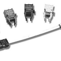
HFBR-0559 Avago Technologies US Inc., HFBR-0559 Datasheet - Page 12

HFBR-0559
Manufacturer Part Number
HFBR-0559
Description
Fiber Optics, Evaluation Kit
Manufacturer
Avago Technologies US Inc.
Datasheet
1.HFBR-0559.pdf
(16 pages)
Specifications of HFBR-0559
Silicon Manufacturer
Avago
Silicon Core Number
HFBR-5903/5903E/5903A
Kit Application Type
Communication & Networking
Application Sub Type
Ethernet Transceiver
Main Purpose
Interface, Ethernet
Embedded
No
Utilized Ic / Part
HFBR-5903, FDDL, Fast Ethernet Transceivers
Primary Attributes
FDDE & Fast Ethernet SFF Transceiver Compatible
Secondary Attributes
SONET OC-3/SDH STM-1
Description/function
Fiber Optic Kit
Lead Free Status / RoHS Status
Lead free / RoHS Compliant
For Use With/related Products
HFCT-5903E
Lead Free Status / RoHS Status
Lead free / RoHS Compliant, Contains lead / RoHS non-compliant
Absolute Maximum Ratings
Stresses in excess of the absolute maximum ratings can cause catastrophic damage to the device. Limits apply to each
parameter in isolation, all other parameters having values within the recommended operating conditions. It should not be
assumed that limiting values of more than one parameter can be applied to the product at the same time. Exposure to the
absolute maximum ratings for extended periods can adversely affect device reliability.
Recommended Operating Conditions
Notes:
A. Ambient Operating Temperature corresponds to transceiver case temperature of 0°C mininum to +85 °C maximum with necessary
B. Ambient Operating Temperature corresponds to transceiver case temperature of -40 °C mininum to +100 °C maximum with necessary
Parameter
Lead Soldering Temperature
Lead Soldering Time
Data Input Voltage
Differential Input Voltage (p-p)
Parameter
HFBR-5903/5903E
HFBR-5903A
Data Input Voltage - Low
Data Input Voltage - High
Data and Signal Detect Output Load
Differential Input Voltage (p-p)
12
Storage Temperature
Supply Voltage
Output Current
Ambient Operating Temperature
Supply Voltage
airflow applied. Recommended case temperature measurement point can be found in Figure 2.
airflow applied. Recommended case temperature measurement point can be found in Figure 2.
Symbol
I
Symbol
R
T
T
t
V
V
V
T
T
V
V
V
V
O
SOLD
S
SOLD
A
A
L
CC
I
D
CC
IL
IH
D
- V
- V
CC
CC
Minimum Typical
-40
-0.5
-0.5
Minimum Typical
0
-40
3.135
-1.810
-1.165
0.800
50
Maximum Unit
10
Maximum Unit
+100
+260
3.6
V
2.0
50
+70
+85
3.465
-1.475
-0.880
CC
°C
°C
sec.
V
V
V
mA
°C
°C
V
V
V
W
V
Reference
Note 1
Reference
Note A
Note B
Note 2


