HFBR-0559 Avago Technologies US Inc., HFBR-0559 Datasheet
HFBR-0559
Specifications of HFBR-0559


Related parts for HFBR-0559


HFBR-0559 Summary of contents
Page 1
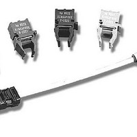
... DIP style with a MT-RJ fiber connector interface. FDDI PMD, ATM and Fast Ethernet 2 km Backbone Links The HFBR-5903 is a 1300 nm product with optical performance compliant with the FDDI PMD standard. The FDDI PMD standard is ISO/IEC 9314-3: 1990 and ANSI X3.166 - 1990. ...
Page 2
... The HFBR-5903 is also useful for both ATM 100 Mb/s interfaces and Fast Ethernet 100 Base-FX interfaces. The ATM Forum User-Network Interface (UNI) Standard, Version 3.0, defines the Physical Layer for 100 Mb/s Multimode Fiber Interface for ATM in Section 2 the FDDI PMD Standard. Likewise, the Fast Ethernet Alliance defines the Physical Layer for 100 Base-FX for Fast Ethernet to be the FDDI PMD Standard ...
Page 3
OVERALL RECEPTACLE CENTER LINE) Case Temperature Measurement Point 9.6 13.59 (0.535) (0.378) MAX. MAX. 12 (0.472) 9.3 9.8 (0.366) (0.386) MAX. MAX. Ø 1.07 (0.042) DIMENSIONS IN MILLIMETERS (INCHES) NOTES: 1. THIS PAGE DESCRIBES THE MAXIMUM ...
Page 4
RX RECEIVER SIGNAL GROUND RECEIVER POWER SUPPLY o 3 SIGNAL DETECT o 4 RECEIVER DATA OUT BAR o RECEIVER DATA OUT 5 Figure 3. Pin Out Diagram. Pin Descriptions: Pin 1 Receiver Signal Ground V RX: ...
Page 5
... The industry convention is 1.5 dB aging for 1300 nm LEDs. The Avago Technologies 1300 nm LEDs will experience less than aging over normal commercial equipment mission life periods. Contact your Avago Technologies sales representative for additional details. 12 HFBR-5903, 62.5/125 µ HFBR-5903 50/125 µ ...
Page 6
... INPUT OPTICAL RISE/FALL TIMES = 1.0/ 2.1 ns. Figure 6. Bit Error Rate vs. Relative Receiver Input Optical Power Ω Ω 130 Ω 1 µ (+3 µ µ Ω Ω Ω HFBR-5903 SERIES CENTER OF SYMBOL - PHY DEVICE V CC (+3.3 V) TD- LVPECL TD+ 130 Ω (+3.3 V) RD+ 100 Ω ...
Page 7
... Note 100 nF Figure 8. Alternative Termination Circuits 7 The HFBR-5900 series of transceivers meet MIL-STD- 883C Method 3015.4 Class 2 products. Care should be used to avoid shorting the receiver data or signal detect outputs directly to ground without proper current limiting impedance. Solder and Wash Process Compatibility The transceivers are delivered with protective process plugs inserted into the MT-RJ connector receptacle ...
Page 8
Board Layout - Decoupling Circuit, Ground Planes and Termination Circuits It is important to take care in the layout of your circuit board to achieve optimum performance from these transceivers. Figure 7 provides a good example of a schematic for ...
Page 9
Regulatory Compliance Table Feature Test Method Electrostatic Discharge MIL-STD-883C (ESD) to the Electrical Pins Method 3015.4 Electrostatic Discharge Variation of ESD) to the MT-RJ Receptacle IEC 801-2 Electromagnetic FCC Class B Interference (EMI) CENELEC CEN55022 VCCI Class 2 Immunity Variation ...
Page 10
... Contact your local Avago Technologies sales representative for details.procedures and results on the Transceiver family, please refer to Applications Note 1075, Testing and Measuring Electromagnetic Compatibility Performance of the HFBR-510X/-520X Fiber Optic Transceivers. Transceiver Reliability and Performance Qualification Data The transceivers have passed Avago Technologies reliability and performance qualification testing and are undergoing ongoing quality and reliability monitoring ...
Page 11
... TIME INTERVAL 0.10 0.025 - 0.0 - 0.025 0.05 5.6 10.0 THE HFBR-5903 OUTPUT OPTICAL PULSE SHAPE SHALL FIT WITHIN THE BOUNDARIES OF THE PULSE ENVELOPE FOR RISE AND FALL TIME MEASUREMENTS. Figure 12. Output Optical Pulse Envelope. -31.0 dBm 1.5 dB < INPUT OPTICAL POWER ( > ...
Page 12
... Data Input Voltage Differential Input Voltage (p-p) Output Current Recommended Operating Conditions Parameter Ambient Operating Temperature HFBR-5903/5903E HFBR-5903A Supply Voltage Data Input Voltage - Low Data Input Voltage - High Data and Signal Detect Output Load Differential Input Voltage (p-p) Notes: A. Ambient Operating Temperature corresponds to transceiver case temperature of 0°C mininum to +85 °C maximum with necessary airflow applied. Recommended case temperature measurement point can be found in Figure 2. B. Ambient Operating Temperature corresponds to transceiver case temperature of -40 ° ...
Page 13
... Supply Current Power Dissipation Data Input Current - Low Data Input Current - High Receiver Electrical Characteristics HFBR-5903/5903E (T = 0°C to +70° HFBR-5903A (T = -40°C to +85° Parameter Supply Current Power Dissipation Data Output Voltage - Low Data Output Voltage - High Data Output Rise Time ...
Page 14
... Data Dependent Jitter Contributed by the Transmitter Random Jitter Contributed by the Transmitter Receiver Optical and Electrical Characteristics HFBR-5903/5903E (T = 0°C to +70° HFBR-5903A (T = -40°C to +85° Parameter Input Optical Power Minimum at Window Edge Input Optical Power Minimum at Eye Center Input Optical Power Maximum ...
Page 15
Notes: 1. This is the maximum voltage that can be applied across the Differential Transmitter Data Inputs to prevent damage to the input ESD protection circuit. The outputs are terminated with 50 Ω connected The power ...
Page 16
FDDI PMD Annex E minimum window time-width of 2.13 ns under worst case input jitter conditions to the Avago Technologies receiver. • Transmitter operating with an IDLE Line State pattern, 125 MBd (62.5 MHz ...