LM5007EVAL National Semiconductor, LM5007EVAL Datasheet - Page 8
LM5007EVAL
Manufacturer Part Number
LM5007EVAL
Description
EVALUATION BOARD KIT, LM5007 SERIES
Manufacturer
National Semiconductor
Datasheet
1.LM5007EVAL.pdf
(12 pages)
Specifications of LM5007EVAL
Svhc
No SVHC (15-Dec-2010)
Development Tool Type
Evaluation Board
Kit Features
12V To 75V Input Range, 90% Measured Efficiency, 10V Output Voltage, 400mA Output Current
Silicon Manufacturer
National Semiconductor
Kit Contents
Board, Datasheet
Features
Thermal Shutdown, Intelligent Current Limit Protection, Highly Efficient Operation
Available stocks
Company
Part Number
Manufacturer
Quantity
Price
Company:

Part Number:
LM5007EVAL/NOPB
Manufacturer:
National Semiconductor
Quantity:
135


www.national.com
ON Time generator and Shutdown
Current Limit
The LM5007 contains an intelligent current limit off timer
intended to reduce the foldback characteristic inherent with
fixed off-time over-current protection. If the current in the
Buck switch exceeds 725mA the present cycle on time is
immediately terminated (cycle by cycle current limit). Follow-
ing the termination of the cycle a non-resetable current limit
off timer is initiated. The duration of the off time is a function
of the external resistor (R
the FB pin voltage equals zero, the current limit off time is
internally preset to 17uS. This condition occurs in short
circuit operation when a maximum amount of off time is
required.
In cases of overload (not complete short circuit) the current
limit off time can be reduced as a function of the output
voltage (measured at the FB pin). Reducing the off time with
smaller overloads reduces the amount of foldback and also
reduces the initial start-up time. The current limit off time for
a given FB pin voltage and R
the following equation:
Applications utilizing low resistance inductors and/or a low
voltage drop rectifier may require special evaluation at high
line, short circuit conditions. In this special case the preset
17uS (FB = 0V) off time may be insufficient to balance the
inductor volt*time product. Additional inductor resistance,
output resistance or a larger voltage drop rectifier may be
necessary to balance the inductor cycle volt*time product
and limit the short circuit current.
N - Channel Buck Switch and
Driver
The LM5007 integrates an N-Channel Buck switch and as-
sociated floating high voltage gate driver. This gate driver
circuit works in conjunction with an external bootstrap ca-
pacitor and an internal high voltage diode. The bootstrap
Toff = 10
-5
/ (0.59 + (V
CI
) and the FB pin voltage. When
CI
FB
resistor can be calculated by
/ 7.22 x 10
-6
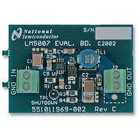
FIGURE 3. Shutdown Implementation
x R
CL
))
(Continued)
8
capacitor is charged by V
diode. A 0.01uF ceramic capacitor connected between the
BST pin and SW pin is recommended.
During each cycle when the Buck switch turns off, the SW
pin is approximately 0V. When the SW pin voltage is low, the
bootstrap capacitor will be charged from Vcc through the
internal diode. The minimum off timer, set to 300ns, ensures
that there will be a minimum interval every cycle to recharge
the bootstrap capacitor.
An external re-circulating diode from the SW pin to ground is
necessary to carry the inductor current after the internal
Buck switch turns off. This external diode must be of the
Ultra-fast or Schottky type to reduce turn-on losses and
current over-shoot. The reverse voltage rating of the re-
circulating diode must be greater than the maximum line
input voltage.
Thermal Protection
Internal Thermal Shutdown circuitry is provided to protect the
integrated circuit in the event the maximum junction tem-
perature is exceeded. When thermal protection is activated,
typically at 165 degrees Celsius, the controller is forced into
a low power reset state, disabling the output driver. This
feature is provided to prevent catastrophic failures from ac-
cidental device overheating.
CC
through the internal high voltage
20078307
Related parts for LM5007EVAL
Image
Part Number
Description
Manufacturer
Datasheet
Request
R

Part Number:
Description:
National Semiconductor [8-Bit D/A Converter]
Manufacturer:
National Semiconductor
Datasheet:
Part Number:
Description:
National Semiconductor [Media Coprocessor]
Manufacturer:
National Semiconductor
Datasheet:
Part Number:
Description:
Digitally Controlled Tone and Volume Circuit with Stereo Audio Power Amplifier, Microphone Preamp Stage and National 3D Sound
Manufacturer:
National Semiconductor
Datasheet:
Part Number:
Description:
Digitally Controlled Tone and Volume Circuit with Stereo Audio Power Amplifier, Microphone Preamp Stage and National 3D Sound
Manufacturer:
National Semiconductor
Datasheet:
Part Number:
Description:
AC97 Rev 2 Codec with Sample Rate Conversion and National 3D Sound
Manufacturer:
National Semiconductor
Part Number:
Description:
Manufacturer:
National Semiconductor
Datasheet:
Part Number:
Description:
Manufacturer:
National Semiconductor
Datasheet:
Part Number:
Description:
General Purpose, Low Voltage, Low Power, Rail-to-Rail Output Operational Amplifiers
Manufacturer:
National Semiconductor
Datasheet:
Part Number:
Description:
8-bit 20 MSPS flash A/D converter.
Manufacturer:
National Semiconductor
Datasheet:
Part Number:
Description:
Low Noise Quad Operational Amplifier
Manufacturer:
National Semiconductor
Datasheet:
Part Number:
Description:
Quad Differential Line Receivers
Manufacturer:
National Semiconductor
Datasheet:
Part Number:
Description:
Quad High Speed Trapezoidal? Bus Transceiver
Manufacturer:
National Semiconductor
Datasheet:
Part Number:
Description:
Dual Line Receiver
Manufacturer:
National Semiconductor
Datasheet:
Part Number:
Description:
TTL to 10k ECL Level Translator with Latch
Manufacturer:
National Semiconductor
Datasheet: