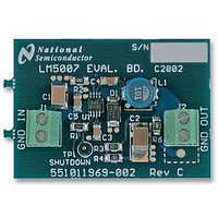
LM5007EVAL National Semiconductor, LM5007EVAL Datasheet - Page 6

LM5007EVAL
Manufacturer Part Number
LM5007EVAL
Description
EVALUATION BOARD KIT, LM5007 SERIES
Manufacturer
National Semiconductor
Datasheet
1.LM5007EVAL.pdf
(12 pages)
Specifications of LM5007EVAL
Svhc
No SVHC (15-Dec-2010)
Development Tool Type
Evaluation Board
Kit Features
12V To 75V Input Range, 90% Measured Efficiency, 10V Output Voltage, 400mA Output Current
Silicon Manufacturer
National Semiconductor
Kit Contents
Board, Datasheet
Features
Thermal Shutdown, Intelligent Current Limit Protection, Highly Efficient Operation
Available stocks
Company
Part Number
Manufacturer
Quantity
Price
Company:
Part Number:
LM5007EVAL/NOPB
Manufacturer:
National Semiconductor
Quantity:
135
www.national.com
Hysteretic Control Circuit
Overview
The output voltage (Vout) can be programmed by two exter-
nal resistors as shown in Figure 1. The regulation point can
be calculated as follows:
The feedback comparator in hysteretic regulators depend
upon the output ripple voltage to switch the output transistor
on and off at regular intervals. In order for the internal
comparator to respond quickly to changes in output voltage,
proportional to inductor current, a minimum amount of ca-
pacitor Equivalent Series Resistance (ESR) is required. A
ripple voltage of 25mV to 50mV is recommended at the
feedback pin (FB) for stable operation. In cases where the
intrinsic capacitor ESR is too small, additional series resis-
tance may be added.
For applications where lower output voltage ripple is re-
quired the load can be connected directly to the low ESR
V
OUT
(Continued)
= 2.5 x (R1 + R2) / R2
FIGURE 1. Low Ripple Output Configuration
6
output capacitor, as shown in Figure 1. The series resistor
(R) will degrade the load regulation. Another technique for
enhancing the ripple voltage at the FB pin is to place a
capacitor in parallel with the feedback divider resistor R1.
The addition of the capacitor reduces the attenuation of the
ripple voltage from the feedback divider
High Voltage Bias Regulator
The LM5007 contains an internal high voltage bias regulator.
The input pin (Vin) can be connected directly to line voltages
from 9 to 75 Volts. To avoid supply voltage transients due to
long lead inductances on the input pin (Vin Pin 8), it is always
recommended to connect low ESR ceramic chip capacitor
() 0.1µF) between "Vin" pin and "RTN" pin (pin 4), located
close to LM5007. The regulator is internally current limited to
10mA. Upon power up, the regulator is enabled and sources
current into an external capacitor connected to the Vcc pin.
When the voltage on the Vcc pin reaches the regulation point
of 7V, the controller output is enabled.
An external auxiliary supply voltage can be applied to the
Vcc pin. If the auxiliary voltage is greater than 7 Volts the
internal regulator will essentially shutoff, thus reducing inter-
nal power dissipation.
20078305


