EVAL-AD7747EBZ Analog Devices Inc, EVAL-AD7747EBZ Datasheet - Page 21
EVAL-AD7747EBZ
Manufacturer Part Number
EVAL-AD7747EBZ
Description
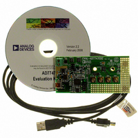
24-Bit Capacitance-to-Digital Converter Eval. Board
Manufacturer
Analog Devices Inc
Specifications of EVAL-AD7747EBZ
Silicon Manufacturer
Analog Devices
Application Sub Type
Capacitance-to-Digital Converter
Kit Application Type
Data Converter
Silicon Core Number
AD7747
Sensor Type
Touch, Capacitive
Interface
I²C
Voltage - Supply
2.7 V ~ 5.25 V
Embedded
No
Utilized Ic / Part
AD7747
Kit Contents
Board
Rohs Compliant
Yes
Lead Free Status / RoHS Status
Lead free / RoHS Compliant
Sensitivity
-
Sensing Range
-
Lead Free Status / RoHS Status
Lead free / RoHS Compliant, Lead free / RoHS Compliant
Available stocks
Company
Part Number
Manufacturer
Quantity
Price
Company:

Part Number:
EVAL-AD7747EBZ
Manufacturer:
Analog Devices Inc
Quantity:
135


CIRCUIT DESCRIPTION
CIN1(+)
OVERVIEW
The AD7747 core is a high precision converter consisting of a
second-order (Σ-Δ or charge balancing) modulator and a third-
order digital filter. It works as a CDC for the capacitive inputs
and as a classic ADC for the voltage input or for the voltage
from a temperature sensor.
In addition to the converter, the AD7747 integrates a multi-
plexer, an excitation source and CAPDACs for the capacitive
inputs, a temperature sensor and a voltage reference for the
voltage and temperature inputs, a complete clock generator,
a control and calibration logic, and an I
interface.
CAPACITANCE-TO-DIGITAL CONVERTER
Figure 25 shows the CDC simplified functional diagram. The
measured capacitance C
lator input and ground. A square-wave excitation signal is
applied on the C
continuously samples the charge going through the C
digital filter processes the modulator output, which is a stream
of 0s and 1s containing the information in 0 and 1 density. The
data from the digital filter is scaled, applying the calibration
coefficients, and the final result can be read through the serial
interface.
CIN1(–)
VIN(+)
VIN(–)
SHLD
C
X
SENSOR
EXCITATION
TEMP
SHLD
CIN
Figure 25. CDC Simplified Block Diagram
X
Figure 24. AD7747 Block Diagram
during the conversion and the modulator
MUX
CAPACITANCE TO DIGITAL CONVERTER
CAP DAC 1
CAP DAC 2
MODULATOR
X
GENERATOR
24-BIT Σ-Δ
EXCITATION
is connected between the Σ-Δ modu-
REFIN(+)
CLOCK
GENERATOR
24-BIT Σ-Δ
GENERATOR
CLOCK
(CDC)
REFIN(–)
DIGITAL
FILTER
2
C-compatible serial
DIGITAL
FILTER
REFERENCE
CONTROL LOGIC
VOLTAGE
CALIBRATION
DATA
VDD
GND
AD7747
INTERFACE
SERIAL
I
2
X
C
. The
Rev. 0 | Page 21 of 28
SDA
SCL
RDY
ACTIVE AC SHIELD CONCEPT
The AD7747 measures capacitance between CIN and ground.
That means any capacitance to ground on signal path between
the AD7747 CIN pin(s) and sensor is included in the AD7747
conversion result.
The parasitic capacitance of the sensor connections can easily
be in the same, if not even higher, order as the capacitance of
the sensor itself. If that parasitic capacitance is stable, it can be
treated as a nonchanging capacitive offset. However, the para-
sitic capacitance of sensor connections is often changing as a
result of mechanical movement, changing ambient temperature,
ambient humidity, etc. These changes are seen as drift in the
conversion result and may significantly compromise the system
accuracy.
To eliminate the CIN parasitic capacitance to ground, the
AD7747 SHLD signal can be used for shielding the connection
between the sensor and CIN, as shown in Figure 25. The SHLD
output is basically the same signal waveform as the excitation of
the CIN pin; the SHLD is driven to the same voltage potential
as the CIN pin. Therefore, there is no ac current between CIN
and SHLD pins, and any capacitance between these pins does
not affect the CIN charge transfer. Ideally, the CIN to SHLD
capacitance does not have any contribution to the AD7747 result.
To get the best result, locate the AD7747 as close as possible to
the capacitive sensor. Keep the connection between the sensor
and AD7747 CIN pin, and also the return path between sensor
ground and the AD7747 GND pin, short. Shield the PCB track
to the CIN pin and connect the shielding to the AD7747 SHLD
pin. In addition, if a shielded cable is used for sensor connection,
the shield should be connected to the AD7747 SHLD pin.
CAPDAC
The AD7747 CDC full-scale input range is ±8.192 pF. For sim-
plicity of calculation, however, the following text and figures use
±8 pF. The part can accept a higher capacitance on the input
and the common-mode or offset (nonchanging component)
capacitance can be balanced by programmable on-chip CAPDACs.
C
X
C
Y
CIN(+)
CIN(–)
SHLD
Figure 26. Using a CAPDAC
CAPDAC(+)
CAPDAC(–)
CDC
AD7747
DATA
Related parts for EVAL-AD7747EBZ
Image
Part Number
Description
Manufacturer
Datasheet
Request
R


Part Number:
Description:
BOARD EVAL FOR SI270X-A
Manufacturer:
Silicon Laboratories Inc
Datasheet:

Part Number:
Description:
BUCK CONV REF DESIGN KIT IP1201
Manufacturer:
International Rectifier
Datasheet:
Part Number:
Description:
BOARD DEMO SYNC DUAL BUCK CNVTER
Manufacturer:
International Rectifier
Datasheet:
Part Number:
Description:
BOARD DEMO SYNC BUCK CONVETER
Manufacturer:
International Rectifier
Datasheet:

Part Number:
Description:
EVALBOARD/EB Omnidirectional microphone - Analog
Manufacturer:
Analog Devices
Datasheet:
Part Number:
Description:
EVALBOARD/EB Omnidirectional microphone - Analog
Manufacturer:
Analog Devices
Datasheet:


Part Number:
Description:
BOARD EVAL LED DRIVER LT3756
Manufacturer:
Linear Technology
Datasheet:

Part Number:
Description:
BOARD EVAL FOR AD7741/7742
Manufacturer:
Analog Devices Inc
Datasheet:

Part Number:
Description:
±1.7g Dual-Axis IMEMS Accelerometer Evaluation Board
Manufacturer:
Analog Devices Inc
Datasheet:

Part Number:
Description:
IC MULTIPLIER ANALOG 8-SOIC T/R
Manufacturer:
Analog Devices Inc
Datasheet:

Part Number:
Description:
IC ANALOG MULTIPLIER 8-DIP
Manufacturer:
Analog Devices Inc
Datasheet:
Part Number:
Description:
IC ANALOG MULTIPLIER 8-SOIC
Manufacturer:
Analog Devices Inc
Datasheet:
Part Number:
Description:
IC ANALOG MULTIPLIER 8-DIP
Manufacturer:
Analog Devices Inc
Datasheet: