ER900TS EASY RADIO, ER900TS Datasheet - Page 20
ER900TS
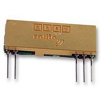
Manufacturer Part Number
ER900TS
Description
MODULE, TX, FM, 860-920MHZ
Manufacturer
EASY RADIO
Datasheet
1.ER400TRS.pdf
(30 pages)
Specifications of ER900TS
External Depth
3.8mm
External Length / Height
12.5mm
External Width
32mm
Frequency
868MHz
Operating Temperature Max
65°C
Operating Temperature Min
-20°C
Output Power
10mW
Range
150m


PCB Layout
The Ground (0 Volt) pins of the receiver should be connected to a substantial ground plane (large area of
PCB copper) connected to 0 Volt. It is suggested that a double sided PCB be used with one layer being the
ground plane.
Power Supply
The supply used to power the receiver should be ‘clean’ and free from ripple and noise (<20mV p-p total). It
is suggested that 100nF ceramic capacitors be used to de-couple the supply close to the power pins of the
receiver. The use of ‘switch mode’ power supplies should be avoided as they can generate both conducted
and radiated high frequency noise that can be very difficult to eliminate. This noise may considerably reduce
the performance of any radio device that is connected or adjacent to the supply.
Antennas
The receiver can be used with the various common types of antenna that match the 50Ω RF Input/Output
such as a monopole (whip), helical or PCB/Wire loop antennas.
Monopole antennas are resonant with a length corresponding to one quarter of the electrical wavelength
(λ/4). They are very easy to implement and can simply be a ‘piece of wire’ or PCB track which at 434MHz
should be 16.4cms in length. This should be straight, in ‘free space’ (kept well away from all other circuitry)
and should be connected directly to the Antenna pin of the receiver. If the antenna is remote it should be
connected via a 50Ω coaxial feeder cable or transmission line. A 50Ω transmission line can be constructed
on FR4 board material by using a 3mm wide PCB track over a ground plane. This should be kept as short as
possible.
Helical antennas are also resonant and generally chosen for their more compact dimensions. They are more
difficult to optimise than monopole antennas and are critical with regard to surrounding objects that can
easily ‘de-tune’ them. They operate most efficiently when there is a substantial ground plane for them to
radiate against.
Wire or PCB Loop antennas are the most compact antennas but are less effective than the other types. They
are also more difficult to design and must be carefully ‘tuned’ for best performance.
The Internet can provide much useful information on the design of Short Range Device (SRD) Antennas.
LPRS Data Sheet
ERx00-02 Series V2.3
Datasheet Revision 2.3 Sept 2005
ER400TS Transmitter, ER400RS Receiver & ER400TRS Transceiver
ER900TS Transmitter, ER900RS Receiver & ER900TRS Transceiver
Easy-Radio ‘02’ (2
Copyright LPRS 2005.
nd
Generation Modules)
Page 20 of 30
Related parts for ER900TS
Image
Part Number
Description
Manufacturer
Datasheet
Request
R

Part Number:
Description:
EVALUATION KIT, EASY RADIO
Manufacturer:
EASY RADIO
Datasheet:

Part Number:
Description:
MODULE, RECEIVER, EASY RADIO
Manufacturer:
EASY RADIO
Datasheet:

Part Number:
Description:
TRANSMITTER, EASY RADIO, 2BUTTON, 434MHZ
Manufacturer:
EASY RADIO
Datasheet:

Part Number:
Description:
MODULE, RX, FM, 433MHZ
Manufacturer:
EASY RADIO
Datasheet:

Part Number:
Description:
MODULE, TX, 433MHZ
Manufacturer:
EASY RADIO
Datasheet: