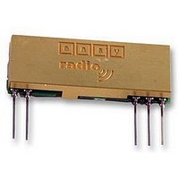
ER900TS EASY RADIO, ER900TS Datasheet - Page 12

ER900TS
Manufacturer Part Number
ER900TS
Description
MODULE, TX, FM, 860-920MHZ
Manufacturer
EASY RADIO
Datasheet
1.ER400TRS.pdf
(30 pages)
Specifications of ER900TS
External Depth
3.8mm
External Length / Height
12.5mm
External Width
32mm
Frequency
868MHz
Operating Temperature Max
65°C
Operating Temperature Min
-20°C
Output Power
10mW
Range
150m
Application & Operation ERx00TRS-02
Figure 9 shows a typical system block diagram comprising hosts (user’s application) connected to Easy-
Radio Transceivers. The hosts (A & B) will be monitoring (collecting data) and/or controlling (sending data) to
some real world application.
The hosts provide serial data input and output lines and two ‘handshaking’ lines that control the flow of data
to and from the Easy-Radio Transceivers. The ‘Busy’ output line, when active, indicates that the transceiver
is undertaking an internal task and is not ready to receive serial data. The ‘Host Ready’ input is used to
indicate that the host is ready to receive the data held in the buffer of the Easy-Radio Transceiver.
The host should check before sending data that the ‘Busy’ line is not high, as this would indicate that the
transceiver is either transmitting or receiving data over the radio link. It should also pull the ‘Host Ready’ line
low and check that no data appears on the Serial Data Output line.
Detailed operation of interfacing, handshaking (including timing) is described in the ‘Easy-Radio Software
Guide’.
Timing Specifications – Applies to all Easy-Radio Modules.
Notes
LPRS Data Sheet
Parameters
Host Serial Input/Output
Host Character Format
End of Data Delay
RF Transmit
Buffer Size
ERx00-02 Series V2.3
1. Data is inverted i.e. Start Bit is logic low. The inputs are intended for direct connection to a
2. 1 start, 8 data, 1 stop = 10 bits @ 104uS/bit = 0.52mS/character at 19200 Baud. (Default)
3. The ‘End of Data’ delay is fixed at twice the character time.
4. A fixed package overhead of 13.2mS is added to all packets.
5. The buffer size is limited to 180 bytes. Sending more than 180 bytes will cause loss of data.
microcontroller UART or to RS232 inputs and outputs via an RS232 Level translator such as a
Maxim MAX232, which invert the logic of the RS232 signals. This allows direct connection to, for
example a Microcontroller UART. The data rate is user programmable (Default 19200 baud) and
may differ between individual units within a system. (See Application Circuit diagram for logic level to
RS232 interface figure 11).
a. Some Custom BAUD rates require 2 stop bits, otherwise some characters may be lost.
b. If parity is used, substitute in the above calculation using 11 bits.
a. CTS pin will go high 2 bytes before the buffer is full. This allows characters already sent to
Host
(A)
be accepted by the ER module.
Datasheet Revision 2.3 Sept 2005
Serial Data Output
Serial Data Input
Host Ready
Busy
Figure 9 Typical System Block Diagram
ER400TS Transmitter, ER400RS Receiver & ER400TRS Transceiver
ER900TS Transmitter, ER900RS Receiver & ER900TRS Transceiver
1 Start, 8 Data, No Parity, 1 Stop
2 x BAUD BYTE Duration
Min
2400, 4800, 9600, 19200, 38400 + Custom
13.2 + (n Bytes X 0.8)
1-180
Transceiver
Easy-Radio
(A)
Easy-Radio ‘02’ (2
RF Link
Copyright LPRS 2005.
nd
Generation Modules)
Transceiver
Easy-Radio
(B)
Units
baud
Bits
mS
mS
Bytes
Serial Data Output
Serial Data Input
Host Ready
Busy
1
Notes
2 &2a
3
4
5
Host
(B)
Page 12 of 30


