210-525NR1 RF Solutions, 210-525NR1 Datasheet - Page 6
210-525NR1
Manufacturer Part Number
210-525NR1
Description
RECEIVER, DIN RAIL, 16CH
Manufacturer
RF Solutions
Datasheet
1.210-525NR1.pdf
(11 pages)
Specifications of 210-525NR1
Svhc
No SVHC (15-Dec-2010)


DS200-11 March ’06
1.5
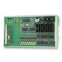
A range of ‘200’ series output modules are available which can be plugged into the 210 Receiver via the four
IDC header boxes on the receiver. The selection of output module will be dependant on the application. Please
see DS200S-1 for a summary the available modules.
1.6
The 210Rx has a 200mm flying lead cable (50ohm) with a panel mount BNC socket provided to mount on an
enclosure. This cable may be extended however please note that typically there is a 50% range reduction
with every 3metres of coax cable used!
For increasing range performance a +3dB gain antenna is available. This is supplied with wall mounting
bracket and 2metres of coax cable, it plugs in directly to the 210Rx BNC connector.
1.7
The antenna choice and position directly controls the system range. Keep it clear of other metal in the system.
The best position by far, is protruding from the top of the product. This is often not desirable for practical or
ergonomic reasons and thus a compromise may be needed. If an internal antenna must be used then try to
keep it away from other metal items, and in particular large ones like transformers, batteries and PCB tracks
and earth planes.
Note that the space around the antenna is as important as the antenna itself. All radio systems are dependant
on a radio signal being received through airspace.
The range quoted is the optimal in direct line of sight without obstacles and in good atmospheric conditions.
Range is affected by many things, for example local environmental conditions, atmospheric conditions,
interference from other radio transmitters. For evaluating the local environment please see our RF Meter
(DS006)
In very worse case applications the range quoted may be reduced to 30% of the optimal range stated.
1.8
In systems where many encoders are in close proximity there may be occasions when, due to signal overlay
between encoders, it is difficult or impossible to guarantee system integrity. In such circumstances it is the
responsibility of the installer to ensure that the system performance is adequate for the purposes of the
installation.
1.9
All products are supplied with their relevant datasheets. These are also available for download from the website
or on request from RF Solutions Ltd.
Information contained in this document is believed to be accurate, however no representation or warranty is given and R.F. Solutions Ltd. assumes no liability with respect to the accuracy of such information.
Connecting output Modules to the 210 Receiver
Connecting an Antenna
Range
Signal integrity
Information availability
Modular Radio Telemetry System
Email sales@rfsolutions.co.uk
Use of R.F.Solutions as critical components in life support systems is not authorised except with express written approval from R.F.Solutions Ltd.
All Trademarks acknowledged and remain the property of the respected owners
Tel +44 (0)1273 898 000
Unit 21, Cliffe Industrial Estate, South Street, Lewes,
©2005 RF Solutions Ltd, www.rfsolutions.co.uk
RF Solutions is a member of the Low Power Radio Association
Tel 01273 898000 Fax 01273 480661
E. Sussex, BN8 6JL, England
R. F. Solutions Ltd.,
Fax +44 (0)1273 480 661
http://www.rfsolutions.co.uk
Page 6
200 Series
Related parts for 210-525NR1
Image
Part Number
Description
Manufacturer
Datasheet
Request
R

Part Number:
Description:
CONTACT BATTERY DUAL FOR A/AA
Manufacturer:
Keystone Electronics
Datasheet:

Part Number:
Description:
Metal Film Resistors - Through Hole 1/3 WATT 210 OHM 1%
Manufacturer:
Vishay

Part Number:
Description:
Thin Film Resistors - SMD 210 0.1% 10PPM
Manufacturer:
Xicon

Part Number:
Description:
IC SOCKET 8DIP .300 TIN
Manufacturer:
Mill-Max Manufacturing Corp.
Datasheet:

Part Number:
Description:
IC ENCODER TRANSMITTER RF 8DIP
Manufacturer:
RF Solutions
Datasheet:

Part Number:
Description:
IC DECODER RECEIVER RF 18DIP
Manufacturer:
RF Solutions
Datasheet:

Part Number:
Description:
IC ENCODER 3 DGTL I/O SOT23-6
Manufacturer:
RF Solutions
Datasheet:

Part Number:
Description:
IC ENCODER 3 DGTL I/O 8-PDIP
Manufacturer:
RF Solutions
Datasheet:

Part Number:
Description:
IC DECODER 3 DGTL I/O 8-PDIP
Manufacturer:
RF Solutions
Datasheet:

Part Number:
Description:
IC DECODER 3 DGTL I/O 8-SOIC
Manufacturer:
RF Solutions
Datasheet:
Part Number:
Description:
118 SERIES AM REMOTE CONTROL SYSTEMS.
Manufacturer:
RF Solutions Ltd.