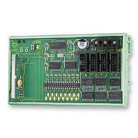
210-525NR1 RF Solutions, 210-525NR1 Datasheet

210-525NR1
Specifications of 210-525NR1
Related parts for 210-525NR1
210-525NR1 Summary of contents
Page 1
... Upto 200 metres at 433MHz Upto 1,000 metres at 433MHz Narrow Band. Upto 6,000 metres at 458MHz • Requires no radio license • Relay Outputs upto 30A @ 230Vac • All Modules supplied with Antenna ©2005 RF Solutions Ltd, www.rfsolutions.co.uk Tel 01273 898000 Fax 01273 480661 200 Series Page 1 ...
Page 2
... Low Power Battery Version Part Number 210-433FR FM Receiver 210-525NR FM Narrow Band Receiver 210-458FR FM High Power REceiver Output Modules • Connect Directly to 210 Rx (Cable Supplied) • no power connections required Part Number 211 Darlington Driver Outputs 215 216 230 DS200-11 March ’06 ...
Page 3
... Use of R.F.Solutions products as critical components in life support systems is not authorised except with express written approval from R.F.Solutions Ltd. DS200-11 March ’06 Description R. F. Solutions Ltd., E Sussex, BN8 6JL. England Fax +44 (0)1273 480 661 RF Solutions is a member of the Low Power Radio Association ©2005 RF Solutions Ltd, www.rfsolutions.co.uk Tel 01273 898000 Fax 01273 480661 200 Series http://www.rfsolutions.co.uk Page 3 ...
Page 4
... When the ‘Auto Tx’ link is made, the 200/201 Tx automatically transmits its data once within every 5 second period, in addition, channel 16 is allocated as a ‘system watchdog‘. As long as the 210Rx continues to receive this signal then output ‘16’ is held ON. If for any reason (fault or RF interference) the signal is not received for approx 20secs then output ‘ ...
Page 5
... On the 210Rx Ensure option link J8 is open. 3. Apply power to the 210Rx, note that LED2 flashes 5 times to show it is configured for use with 200Tx transmitters. 4. Briefly press the 210Rx Learn Switch: Note that the 210Rx Learn LED (LED 17) will flash. ...
Page 6
... DS200S-1 for a summary the available modules. 1.6 Connecting an Antenna The 210Rx has a 200mm flying lead cable (50ohm) with a panel mount BNC socket provided to mount on an enclosure. This cable may be extended however please note that typically there is a 50% range reduction with every 3metres of coax cable used! For increasing range performance a +3dB gain antenna is available ...
Page 7
... I/P 3 I/P 4 200/201 Auto Tx Enable 1-8 Transmitter I/P 5 I/P 6 I Zero Volt Inputs Range** Freq Compatible (Metres) (MHz) Decoders 200 433.92 210-433F 1,000 434.525 210-525N 6,000 458.850 210-458F 1,000 434.525 210- 525N 6,000 458.850 210-458F Page 7 BNC Socket 24Vdc Supply ...
Page 8
... R. F. Solutions Ltd., Unit 21, Cliffe Industrial Estate, South Street, Lewes, E. Sussex, BN8 6JL, England Tel +44 (0)1273 898 000 Fax +44 (0)1273 480 661 RF Solutions is a member of the Low Power Radio Association ©2005 RF Solutions Ltd, www.rfsolutions.co.uk Tel 01273 898000 Fax 01273 480661 200 Series Typical ...
Page 9
... Storage Temperature: - +55 Celsius. Electrical Characteristics Supply Voltage: 12V Supply Supply Voltage: 24V Supply Supply Current : Quiescent Time from Tx Switch depressed to 210Rx output Time from Tx Switch release to Decoder output Switched output Voltage (I out = 1mA) Logic Low Logic High Part Numbering Part No 210-433FR Receiver Decoder 16 Channels DIN Rail Mounting 433 ...
Page 10
... Total cumulative output of module 1A @50Vdc The only connections required are • Screw terminals to connect to each channel output. • Direct connection to the 210 Receiver via the four ribbon cables / connectors supplied. Dimensions: Within DIN Rail 82mm Storage Temperature: -10 to +70 Electrical Characteristics Supply Voltage Output voltage ...
Page 11
... RF Solutions is a member of the Low Power Radio Association ©2005 RF Solutions Ltd, www.rfsolutions.co.uk Tel 01273 898000 Fax 01273 480661 200 Series 210 Rx 216 o Celsius. Typical Max From 210Rx module 5 12 210 Rx 230 o Celsius. Typical Max From 210Rx module 30 20 http://www.rfsolutions.co.uk Page 11 Relay Outputs Units A Relay Outputs Units A A ...


