CNY17F-3X001 Vishay, CNY17F-3X001 Datasheet
CNY17F-3X001
Specifications of CNY17F-3X001
Available stocks


Related parts for CNY17F-3X001


CNY17F-3X001 Summary of contents
Page 1
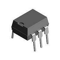
... 18216 DESCRIPTION The CNY17F is an optocoupler consisting of a gallium arsenide infrared emitting diode optically coupled to a silicon planar phototransistor detector in a plastic plug-in DIP-6 package. The coupling device is suitable for signal transmission between two electrically separated circuits. The potential difference between the circuits to be coupled is not allowed to exceed the maximum permissible reference voltages ...
Page 2
... CNY17F Vishay Semiconductors ABSOLUTE MAXIMUM RATINGS PARAMETER INPUT Reverse voltage DC forward current Surge forward current Power dissipation OUTPUT Collector emitter breakdown voltage Collector current Total power dissipation COUPLER Isolation test voltage between emitter and detector referred to standard climate 23/50 DIN 50014 ...
Page 3
... Cut-off frequency Document Number: 83607 For technical questions, contact: optocoupler.answers@vishay.com Rev. 1.5, 07-May-08 no Base Connection TEST CONDITION PART mA 2 CNY17F-1 CNY17F CNY17F-3 CNY17F-4 PART SYMBOL CNY17F-1 CNY17F CNY17F-3 CNY17F-4 CNY17F-1 CNY17F 1 CNY17F-3 CNY17F-4 TEST CONDITION PART = Ω mA 5 Ω mA 5 Ω mA ...
Page 4
... For technical questions, contact: optocoupler.answers@vishay.com 224 Optocoupler, Phototransistor Output, no Base Connection TEST CONDITION PART CNY17F-1 F CNY17F CNY17F CNY17F CNY17F-1 F CNY17F CNY17F CNY17F CNY17F-1 F CNY17F CNY17F CNY17F CNY17F-1 F CNY17F CNY17F CNY17F Ω icny17f_02 SYMBOL MIN. TYP. MAX 3.0 ...
Page 5
... Rev. 1.5, 07-May-08 no Base Connection = Fig Current Transfer Ratio (CTR) vs. Temperature CNY17F Vishay Semiconductors 1000 ( ˚ 100 0 (mA) icny17f_06 F Fig Current Transfer Ratio vs. Diode Current 1000 ( ˚ 100 (mA) icny17f_07 F Fig Current Transfer Ratio vs. Diode Current 1000 ( mA ( 100 (°C) icny17f_08 A www.vishay.com 225 ...
Page 6
... CNY17F Vishay Semiconductors ° (V) icny17f_09 CE Fig Output Characteristics CNY17F- 1.1 1.0 0.9 0 (mA) F icny17f_10 Fig Forward Voltage (V,T) CEO ( ° 0 0.01 0.001 (°C) icny17f_11 A Fig Collector Emitter Off-state Current www.vishay.com For technical questions, contact: optocoupler.answers@vishay.com 226 Optocoupler, Phototransistor Output, no Base Connection ...
Page 7
... Optocoupler, Phototransistor Output, 1.0 0 °C) CEsat C A 0.8 0.7 0 0.5 0.4 0 0.2 0 (mA) icny17f_15 C Fig Saturation Voltage vs. Collector Current and Modulation Depth CNY17F 0.005 0. parameter ° 0.1 0.2 0 (s) icny17f_16 p Fig Permissible Pulse Load 200 tot A 150 Transistor 100 Diode ...
Page 8
... CNY17F Vishay Semiconductors PACKAGE DIMENSIONS in inches (millimeters) 0.248 (6.30) 0.256 (6.50) 0.039 (1.00) min. 4° typ. 0.018 (0.45) 0.022 (0.55) i178004 Option 6 0.407 (10.36) 0.391 (9.96) 0.307 (7.8) 0.291 (7.4) 0.028 (0.7) 0.014 (0.35) 0.010 (0.25) 0.400 (10.16) 0.430 (10.92) www.vishay.com For technical questions, contact: optocoupler ...
Page 9
... Vishay Semiconductor GmbH, P.O.B. 3535, D-74025 Heilbronn, Germany Document Number: 83607 For technical questions, contact: optocoupler.answers@vishay.com Rev. 1.5, 07-May-08 no Base Connection and may do so without further notice. CNY17F Vishay Semiconductors www.vishay.com 229 ...
Page 10
... Information contained herein is intended to provide a product description only. No license, express or implied, by estoppel or otherwise, to any intellectual property rights is granted by this document. Except as provided in Vishay's terms and conditions of sale for such products, Vishay assumes no liability whatsoever, and disclaims any express or implied warranty, relating to sale and/or use of Vishay products including liability or warranties relating to fitness for a particular purpose, merchantability, or infringement of any patent, copyright, or other intellectual property right ...
Page 11
... BRT Il ILD ILQ SFH6 VO Examples: CNY17F-2X017T 4N35-X016 SFH615-3X001 VO615A-9X007T This field is always 4 characters long and commences with the character X. In the case of surface mounted products in Tape and Reel format, the tape and reel option character “T” will follow this field. The possible combinations for these ...
Page 12
... IEC climatic category (DIN IEC 60068 Part 1/9.80) Pollution degree (DIN VDE 0110 Part 1/1.89) (1) Maximum operation insulating voltage (1) Test voltage input/output, procedure 1.875 routine 100 % test, Pr IORM partial discharge < www.vishay.com For technical questions, contact: optocoupler.answers@vishay.com 2 Option Information V INITIA kV/µ IORM ...
Page 13
... For technical questions, contact: optocoupler.answers@vishay.com Rev. 1.7, 11-Sep-07 Option Information SYMBOL IOTM V INITIAL ° Δ SYMBOL 4N25/26/27/28 4N35/36/37/38/39 4N32/33 CNY17-.. CNY17F-.. H11A-.. H11AA1-.. H11B-.. H11B1-.. H11C-.. H11D-.. IL1/2/5/74 IL2B-.. IL30/31/55 IL55B-.. IL66-.. IL66B-.. IL201/202/203 V IORM Option Information Vishay Semiconductors SYSTEM 1 UNIT 1335 8000 8000 ...
Page 14
... Package temperature Current (input current ° Derating with higher ambient temperature Power (output or total power dissipation, T Derating with higher ambient temperature Insulation resistance 500 V Si I/O www.vishay.com For technical questions, contact: optocoupler.answers@vishay.com 4 Option Information SYMBOL V IOTM V INITIAL ° ΔP ...
Page 15
... Reinforced insulation operating voltage of 400 RMS Document Number: 83713 For technical questions, contact: optocoupler.answers@vishay.com Rev. 1.7, 11-Sep-07 Option Information During the soldering process, the package should not be wetted with tin-lead solder to prevent the impairment of the isolation features. Apart from iron soldering, only reflow soldering methods (vapor phase, infrared and hot gas) are permissible ...
Page 16
... During the soldering process, the package should not be wetted with tin-lead solder to prevent the impairment of the isolation features. Apart from iron soldering, only reflow soldering methods (vapor phase, infrared and hot gas) are www.vishay.com For technical questions, contact: optocoupler.answers@vishay.com 6 Option Information permissible. Permissible soldering conditionsfor SMD bending options: ...