VS-HFA120FA120P Vishay, VS-HFA120FA120P Datasheet - Page 3
VS-HFA120FA120P
Manufacturer Part Number
VS-HFA120FA120P
Description
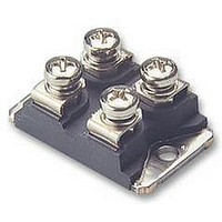
TRANSISTOR,IGBT,1200V,120A,SOT227
Manufacturer
Vishay
Datasheet
1.VS-HFA120FA120P.pdf
(7 pages)
Specifications of VS-HFA120FA120P
Transistor Type
SOT-227
Power Dissipation Max
337W
Operating Temperature Range
-55°C To +150°C
Transistor Case Style
SOT-227
No. Of Pins
4
Lead Free Status / RoHS Status
Lead free / RoHS Compliant


Document Number: 94608
Revision: 22-Jul-10
94608_04
94608_01
1000
100
160
140
120
100
Fig. 1 - Typical Forward Voltage Drop Characteristics
10
80
60
40
20
Fig. 4 - Maximum Allowable Case Temperature vs.
0
1
0.5
94608_03
0
0.0001
0.001
Square wave (D = 0.50)
80 % rated V
See note (1)
I
1.0
F(AV)
0.01
0.1
V
0.00001
1
FM
20
1.5
- Average Forward Current (A)
Average Forward Current
- Forward Voltage Drop (V)
2.0
R
applied
40
DiodesAmericas@vishay.com, DiodesAsia@vishay.com,
2.5
For technical questions within your region, please contact one of the following:
T
T
T
(thermal resistance)
3.0
J
J
J
DC
60
= 150 °C
= 125 °C
= 25 °C
Single pulse
0.0001
3.5
Fig. 3 - Maximum Thermal Impedance Z
Ultrafast Soft Recovery Diode, 120 A
4.0
80
4.5
t
100
1
5.0
- Rectangular Pulse Duration (s)
0.001
HEXFRED
D = 0.75
D = 0.50
D = 0.33
D = 0.25
D = 0.20
94608_02
94608_05
®
0.0001
0.01
0.001
0.01
300
250
200
150
100
thJC
10
0.1
50
0
1
200
DiodesEurope@vishay.com
Characteristics
0
Fig. 2 - Typical Values of Reverse Current vs.
Fig. 5 - Forward Power Loss Characteristics
T
I
F(AV)
J
= 150 °C
400
180°
120°
20
-
90°
60°
30°
V
Average Forward Current (A)
R
T
- Reverse Voltage (V)
J
Reverse Voltage
Vishay Semiconductors
= 125 °C
0.1
600
40
T
J
= 25 °C
DC
HFA120FA120P
800
60
RMS limit
1000
80
1
www.vishay.com
1200
100
3
Related parts for VS-HFA120FA120P
Image
Part Number
Description
Manufacturer
Datasheet
Request
R

Part Number:
Description:
357-036-542-201 CARDEDGE 36POS DL .156 BLK LOPRO
Manufacturer:
Vishay
Datasheet:
Part Number:
Description:
357-036-542-201 CARDEDGE 36POS DL .156 BLK LOPRO
Manufacturer:
Vishay
Datasheet:
Part Number:
Description:
357-036-542-201 CARDEDGE 36POS DL .156 BLK LOPRO
Manufacturer:
Vishay
Datasheet:
Part Number:
Description:
357-036-542-201 CARDEDGE 36POS DL .156 BLK LOPRO
Manufacturer:
Vishay
Datasheet:
Part Number:
Description:
357-036-542-201 CARDEDGE 36POS DL .156 BLK LOPRO
Manufacturer:
Vishay
Datasheet:
Part Number:
Description:
357-036-542-201 CARDEDGE 36POS DL .156 BLK LOPRO
Manufacturer:
Vishay
Datasheet:
Part Number:
Description:
357-036-542-201 CARDEDGE 36POS DL .156 BLK LOPRO
Manufacturer:
Vishay
Datasheet:
Part Number:
Description:
357-036-542-201 CARDEDGE 36POS DL .156 BLK LOPRO
Manufacturer:
Vishay
Datasheet:
Part Number:
Description:
357-036-542-201 CARDEDGE 36POS DL .156 BLK LOPRO
Manufacturer:
Vishay
Datasheet:
Part Number:
Description:
357-036-542-201 CARDEDGE 36POS DL .156 BLK LOPRO
Manufacturer:
Vishay
Datasheet:
Part Number:
Description:
357-036-542-201 CARDEDGE 36POS DL .156 BLK LOPRO
Manufacturer:
Vishay
Datasheet:
Part Number:
Description:
357-036-542-201 CARDEDGE 36POS DL .156 BLK LOPRO
Manufacturer:
Vishay
Datasheet:
Part Number:
Description:
357-036-542-201 CARDEDGE 36POS DL .156 BLK LOPRO
Manufacturer:
Vishay
Datasheet:
Part Number:
Description:
357-036-542-201 CARDEDGE 36POS DL .156 BLK LOPRO
Manufacturer:
Vishay
Datasheet:
Part Number:
Description:
357-036-542-201 CARDEDGE 36POS DL .156 BLK LOPRO
Manufacturer:
Vishay
Datasheet: