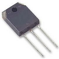
GT10Q101 Toshiba, GT10Q101 Datasheet - Page 5

GT10Q101
Manufacturer Part Number
GT10Q101
Description
IGBT, 1200V, TO-3P(N)
Manufacturer
Toshiba
Specifications of GT10Q101
Transistor Type
IGBT
Dc Collector Current
10A
Collector Emitter Voltage Vces
2.7V
Power Dissipation Max
140W
Collector Emitter Voltage V(br)ceo
1.2kV
Transistor Case Style
TO-3P
No. Of Pins
3
Current Ic
RoHS Compliant
Channel Type
N
Configuration
Single
Collector-emitter Voltage
1.2kV
Gate To Emitter Voltage (max)
±20V
Package Type
TO-3PN
Pin Count
3 +Tab
Mounting
Through Hole
Operating Temperature (max)
150C
Operating Temperature Classification
Military
Power Dissipation Pd
140W
Rohs Compliant
Yes
Svhc
No SVHC
Lead Free Status / Rohs Status
Not Compliant
3000
1000
10
10
10
10
300
100
100
10
10
10
0.5
0.3
0.1
30
10
50
30
10
− 1
− 2
− 3
− 4
0.1
3
5
3
1
2
1
0
10
1
*: Single
Curves must be
derated linearly with
increase in
temperature.
− 5
Common emitter
V GE = 0
f = 1 MHz
Tc = 25°C
I C max (pulsed)*
I C max (continuous)
nonrepetitive
pulse Tc = 25°C
Tc = 25°C
0.3
10
3
Collector-emitter voltage V
Collector-emitter voltage V
− 4
operation
DC
1
10
10
Safe operating area
− 3
Pulse width t
3
R
10
30
C – V
th (t)
− 2
10
100 μs*
– t
CE
100
10
w
w
− 1
1 ms*
30
(s)
300
10
CE
CE
10 ms*
100
0
(V)
(V)
C oes
50 μs*
C ies
C res
1000
10
1
1000
3000
10
2
5
1000
800
600
400
200
0.5
0.3
0.1
50
30
10
0
5
3
1
0
1
Common emitter
R L = 60 Ω
Tc = 25°C
T j < = 125°C
V GE = ±15 V
R G = 75 Ω
3
Collector-emitter voltage V
20
V CE = 200 V
Gate charge Q
10
600
Reverse bias SOA
V
CE
40
30
, V
400
GE
100
– Q
60
G
G
(nC)
300
CE
80
(V)
1000
GT10Q101
2006-10-31
3000
100
20
16
12
8
4
0


