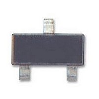
P0102BL STMicroelectronics, P0102BL Datasheet - Page 4

P0102BL
Manufacturer Part Number
P0102BL
Description
SCR THYRISTOR, 170mA, 200V, SOT-23
Manufacturer
STMicroelectronics
Datasheet
1.P0102BL.pdf
(11 pages)
Specifications of P0102BL
Peak Repetitive Off-state Voltage, Vdrm
200V
Gate Trigger Current Max, Igt
0.2mA
Current It Av
170mA
On State Rms Current It(rms)
250mA
Peak Non Rep Surge Current Itsm 50hz
6A
Lead Free Status / RoHS Status
Lead free / RoHS Compliant
Available stocks
Company
Part Number
Manufacturer
Quantity
Price
Company:
Part Number:
P0102BL 5AA4
Manufacturer:
STM
Quantity:
96 000
Part Number:
P0102BL 5AA4
Manufacturer:
ST
Quantity:
20 000
Company:
Part Number:
P0102BL5AA4
Manufacturer:
CYPRESS
Quantity:
103
Part Number:
P0102BL5AA4
Manufacturer:
ST
Quantity:
20 000
Characteristics
Table 6.
1. S = Copper surface under tab.
4/11
Figure 1.
Figure 3.
Symbol
R
R
R
R
1.0
0.9
0.8
0.7
0.6
0.5
0.4
0.3
0.2
0.1
0.0
1.1
0.7
0.4
0.3
th(j-a)
th(j-a)
th(j-a)
1.0
0.9
0.8
0.6
0.5
0.2
0.1
0.0
th(j-t)
0.0
P(W)
0
I
T(AV)
= 180°
Junction to case (DC)
Junction to tab (DC)
Junction to ambient (DC)
Junction to ambient (mounted on FR4 with recommended pad layout) SOT23-3L
(A)
0.1
Thermal resistance
Maximum average power
dissipation vs. average on-state
current P010xxA and P010xxN
Average and DC on-state current
vs. lead temperature
P010xxA and P010xxN
25
D.C. (SOT-223)
= 180° (SOT-223)
0.2
D.C. (TO-92)
50
I
T(AV)
T
lead
0.3
(A)
= 180° (TO-92)
(°C)
75
0.4
100
0.5
Parameter
360°
125
0.6
Figure 2.
Figure 4.
0.30
0.28
0.26
0.24
0.22
0.20
0.18
0.16
0.14
0.12
0.10
0.08
0.06
0.04
0.02
0.00
1.2
1.1
1.0
0.9
0.8
0.7
0.6
0.5
0.4
0.3
0.2
0.1
0.0
0
0.00
I
T(AV)
P(W)
D.C. (TO-92)
S
D.C. (SOT-223)
(1)
= 180°
(A)
0.02
= 5 cm
Maximum average power
dissipation vs. average on-state
current P010xxL
Average and DC on-state current
vs. ambient temperature P010xxA
and P010xxN
25
= 180° (TO-92)
0.04
2
0.06
SOT-223
SOT-223
= 180° (SOT-223)
50
TO-92
TO-92
I
T(AV)
0.08
T
amb
(A)
(°C)
0.10
75
Maximum
0.12
150
400
80
30
60
Device mounted on
FR4 with recomended
pad layout for SOT-223
0.14
100
360°
0.16
P010xx
°C/W
°C/W
°C/W
°C/W
Unit
0.18
125


