IAMA3535 Red Lion Controls, IAMA3535 Datasheet - Page 5
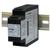
IAMA3535
Manufacturer Part Number
IAMA3535
Description
Isolation Amplifier
Manufacturer
Red Lion Controls
Specifications of IAMA3535
Supply Voltage Ac, Min
0V
Supply Voltage Dc, Min
11V
Width
3.12"
Signal Input Type
Selectable Current Or Voltage
Configuration Setup
DIP Switch
Iso-amp Mounting Type
DIN Rail
Supply Voltage Dc, Max
36V
Input Accuracy
± 0.1% Of FS
Signal Output Type
Selectable Current Or Voltage
Rohs Compliant
Yes
Lead Free Status / RoHS Status
Lead free / RoHS Compliant


GREEN
2.0 INPUT SCALING USING FIELD CONFIGURATION
3.0 OUTPUT SET-UP USING FACTORY CONFIGURATION
V
LED
V
RED
LED
OUT-
I
OUT-
I
I
I
OUT+
OUT+
OUT-
OUT-
1V
1V
I
I
IN
IN
I A M
A
IAMA
IAMA
S
T
A
T
U
S
10
10
4
4
1 2 3
7 8 9
1 2 3
7 8 9
5
5
12
12
6
6
MC2290D
MC2290D
S
T
A
T
U
S
S
T
A
T
U
S
O N
2 0 m
1 0
9
8
7
6
5
4
3
2
1
A /1
IN
O U
IN P
O U
m A
F IE
T F
100V
INPUT
COMM
U T
T P
100V
INPUT
COMM
L D
O U
IE L
~ -
V
U T
~ -
V
R A
10V
/F A
D /F
10V
T P
R A
~ -
N G
C T
~ -
U T
A C
OUT+
N G
OUT+
E
.
T .
E
(AC)
(AC)
DC+
DC+
DC-
(AC)
DC-
(AC)
1
1
1
1
1
1
1
2
2
2
2
2
2
2
3
3
3
3
3
3
Step 3.3 & 3.4
3
4
4
4
4
4
4
4
Step 2.10
Step 2.3
Step 2.4
Step 2.6
Step 2.8
Step 3.5
5
5
5
5
5
5
5
S1
S1
S1
S1
S1
S1
S1
6
6
6
6
6
6
6
7
7
7
7
7
7
7
8
8
8
8
8
8
8
9 10
9 10
9 10
9 10
9 10
9 10
9 10
S2
S2
S2
S2
S2
S2
S2
1
1
1
1
1
1
1
ON
ON
ON
ON
ON
ON
ON
2.1 Remove power.
2.2 Connect signal source to the correct input terminals based on the maximum
2.3 Set Input Range switches (S1 switches 6 through 10) to the desired input range
2.4 Set Input Field/Fact. switch (S1 switch 2) to the off position.
2.5 Apply power to the IAMA and allow a warm up period of five minutes. Follow
2.6 Set Input Field/Fact. switch (S1 switch 2) to the on position.
2.7 Apply desired minimum scale signal.
2.8 Set Input Field/Fact. switch (S1 switch 2) to the off position.
2.9 Apply maximum scale input.
2.10 Set Input Field/Fact. switch (S1 switch 2) to the on position.
2.11 Input scaling complete. Go to Step 3.0 or Step 4.0.
3.1 Remove power.
3.2 For voltage output values, go to Step 3.4
For current output values, continue at Step 3.3
3.3 Set 20 mA/1 mA switch (S2) to desired full scale output.
(20 mA - on; 1 mA - off)
3.4 Set Output Field/Fact. switch (S1 switch 1) to the off position.
3.5 Set Output Range switches (S1 switches 3, 4, and 5) to the desired Output Range
3.6 Connect external device to appropriate IAMA output terminals.
3.7 Apply power to the IAMA and allow a warm up period of five minutes. Output
5
signal input.
(See Table 3). Select the lowest possible range that will support the desired
maximum signal. Example: if the desired span is 20 mV to 85 mV, the best range
selection is 0 to 100 mV. The 0 to 200 mV will also suffice, but the accuracy will
be reduced. (0 to 10 VDC range shown).
the manufacturer’s warm up procedure for the calibration source.
The Red and Green LEDs will alternately blink.
The Red and Green LEDs will alternately blink.
If the signal is equal or below the minimum limit of the selected range, the Red LED
The Red and Green LEDs will alternately blink.
Red LED extinguishes and Green LED becomes solid. Your scaled values are now
Red LED will blink slowly if signal is equal to or below minimum limit and blinks
(See Table 2). (4 to 20 mA range shown)
set-up complete.
Terminal 7: max. signal input 1 VDC
Terminal 8: max. signal input 10 VDC
Terminal 9: max. signal input 100 VDC
Terminal 10: max. signal input 100 mA
Terminal 12: signal common
blinks slowly and the Green LED turns off. Removing power aborts scaling,
begin at Step 2.1.
saved and recalled if the Input Field/Fact. switch (S1 switch 2) is in the on
position when power is applied.
rapidly if signal increases above maximum limit.
Terminal 6: + Voltage
Terminal 5: - Voltage
Terminal 4: + Current
Terminal 1: - Current
Related parts for IAMA3535
Image
Part Number
Description
Manufacturer
Datasheet
Request
R

Part Number:
Description:
Counter
Manufacturer:
Red Lion Controls
Datasheet:
Part Number:
Description:
Miniature Length Sensor
Manufacturer:
Red Lion Controls
Datasheet:
Part Number:
Description:
Model Lsc - Single Channel Output Length Sensor
Manufacturer:
Red Lion Controls
Datasheet: