IAMA3535 Red Lion Controls, IAMA3535 Datasheet - Page 2
IAMA3535
Manufacturer Part Number
IAMA3535
Description
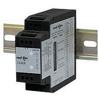
Isolation Amplifier
Manufacturer
Red Lion Controls
Specifications of IAMA3535
Supply Voltage Ac, Min
0V
Supply Voltage Dc, Min
11V
Width
3.12"
Signal Input Type
Selectable Current Or Voltage
Configuration Setup
DIP Switch
Iso-amp Mounting Type
DIN Rail
Supply Voltage Dc, Max
36V
Input Accuracy
± 0.1% Of FS
Signal Output Type
Selectable Current Or Voltage
Rohs Compliant
Yes
Lead Free Status / RoHS Status
Lead free / RoHS Compliant


14. ENVIRONMENTAL CONDITIONS:
15. CERTIFICATIONS AND COMPLIANCES:
16. CONSTRUCTION: Case body is black high impact plastic
17. CONNECTIONS: 14 AWG max
18. MOUNTING: Standard DIN top hat (T) profile rail according to EN50022
19. WEIGHT: 4.5 oz. (127.57 g)
MODULE ISOLATION
combination of optical and transformer isolation. The optical isolation provides
common mode voltage (CMV) isolation up to 1.5 kV between the sensor input and
the process signal output. The IAMA’s power is isolated from the sensor signal
input and the process signal output by a DC/DC transformer isolation circuit.
COMMON
11-36
Immunity to EN 50082-2
Electrostatic discharge
Electromagnetic RF fields
Fast transients (burst)
RF conducted interference
Simulation of cordless telephone
Emissions to EN 50081-2
RF interference
INPUT
Operating Temperature Range: -20 to +65 °C
Storage Temperature Range: -40 to +85 °C
Operating and Storage Humidity: 85% max. relative humidity (non-
Temperature Coefficient: %/C (100 PPM/°C) max.
Vibration according to IEC 68-2-6: Operational 5 to 150 Hz in X, Y, Z
Shock according to IEC 68-2-27: Operational 30 g’s, 11 msec in 3 directions.
Altitude: Up to 2000 meters
SAFETY
ELECTROMAGNETIC COMPATIBILITY
Notes:
1. Self-recoverable loss of performance during EMI disturbance at 10 V/m:
2. Criteria A: No loss of performance within the unit’s specifications.
Refer to EMC Installation Guidelines section of this bulletin for additional
- 35x7.5 and 35 x 15 and G profile rail according to EN50035-G32.
IAMA modules feature “3-Way” Signal Isolation. The 3-Way isolation is a
VDC
*
condensing) from -20 to +65 °C
direction for 1.5 hours, 2 g’s.
UL Recognized Component, File #E179259, UL61010A-1, CSA C22.2
IECEE CB Scheme Test Certificate # US/5141B/UL,
For operation without loss of performance:
information.
V
I
Terminal number is dependent on max. input voltage.
IN
IN
No. 1010-1
Recognized to U.S. and Canadian requirements under the Component
Recognition Program of Underwriters Laboratories, Inc.
CB Scheme Test Report # 01ME11540-0702001
IEC 61010-1, EN 61010-1: Safety requirements for electrical equipment
Analog output signal deviation less than 5% of full scale.
Install power line filter, RLC #LFIL0000 or equivalent on DC power
lines at unit.
Install 2 ferrite cores, RLC #FCOR0000 or equivalent, to DC power
lines at unit.
10
12
3
2
*
Issued by Underwriters Laboratories, Inc.
for measurement, control, and laboratory use, Part 1.
+
-
VARIABLE
SUPPLY
POWER
GAIN
AMP
BLOCK DIAGRAM
CONVERTER
EN 61000-4-2
EN 61000-4-3
EN 61000-4-4
EN 61000-4-6
ENV 50204
EN 55011
V/F
OR
Level 2; 4 Kv contact
Level 3; 8 Kv air
Level 3; 10 V/m
80 MHz - 1 GHz
Level 4; 2 Kv I/O
Level 3; 2 Kv power
Level 3; 10 V/rms
150 KHz - 80 MHz
Level 3; 10 V/m
900 MHz 5 MHz
200 Hz, 50% duty cycle
Enclosure class A
Power mains class A
PROCESS
CIRCUITRY
CIRCUITY
PWM
6
5
4
1
1
2
V
V
I
I
OUT+
OUT-
OUT+
OUT-
2
2
OVERVIEW
provides a linearly proportional voltage or current output, while the IAMA6262
transmits the scaled square root of the input signal. This allows the IAMA6262
to provide a signal that is linear to flow rate in applications utilizing a differential
pressure transducer. Both units have two modes of operation known as Factory
and Field modes. Factory mode is used when the default input and output ranges
are suitable. Field mode can be independently selected for both the input and
output, and allows the user to custom calibrate, or scale the signal. If Factory
mode is selected, the IAMAs use factory presets for the selected input or output
range. If Field mode is selected, the IAMAs can be custom scaled within a
selected input or output range. Field mode also allows the IAMA to reverse its
output in relation to its input.
and output ranges. The factory calibration values are permanently stored in
E
factory checksum error occurs. See Factory Recalibration for details. Field
scaling is achieved by applying minimum and full scale values from a
calibration source and storing the values by a single DIP switch transition. Field
scaling is available for all input and output ranges and the values are permanently
stored in E
modes for a particular range, which restores the respective setting. The Factory
and Field E
IAMA is received from the factory. Therefore, until the IAMA is field scaled,
factory and field modes perform identically. See SCALING PROCEDURE for
detailed instructions on field programming the IAMA.
extent of the selected range. The closer together the minimum and full scale
values are to each other, the less accurate the signal will be. For example, if the
0 to 1 V input range is selected, and the unit is scaled for 0 to 0.5 V, the signal
has the same resolution as the 0 to 1 V range. Since this resolution will be two
times the percentage of span for 0.5 V, more accuracy can be achieved by using
the 0 to 0.5 V range.
span, but the IAMA will not update the output beyond 10% over range.
normal operation. Table 1, LED Indications, details the LED indications for
various unit conditions.
industrial environments. Suppressor diodes protect both input and output
circuits from wiring errors and transient high voltage conditions.
INPUTS
convert these signals to common industrial control signals. The input signal
combinations are configured by making specific DIP switch selections on the 10
position DIP switch.
OUTPUTS
switch selectable. A 1 position DIP switch is used to select between the 1 mA/20
mA output ranges. The maximum output current signal is 22 mA with 600
output resistance and the maximum output voltage signal is 11 V with 1 K
output resistance.
ZERO AND SPAN
transitioning S1-2 to store that value. Next, the full scale value is applied and the
DIP switch transition stores the value. The output scaling is performed in a
similar manner but the output is driven to the desired minimum and full scale
values by the calibration source applied to the input. S1-1 is used to store the
minimum and full scale output values.
ILLEGAL RANGE SELECTIONS AND CHANGES
or output range is selected when power is applied the output is set to approximately
0 VDC and the red LED indicates the error according to Table 1. Power must be
removed and valid ranges selected for the IAMA to operate properly.
LED indicates a range change according to Table 1, LED Indications and the
output goes to the previously stored range minimum scale value. Normal
operation will be resumed if the switches are placed back in the previous
positions or power is removed and restored.
2
PROM and should not be changed in the field, unless unacceptable error or a
The IAMA3535 continuously monitors a voltage or current input and
The units are factory precalibrated for minimum and full scale for all input
After field scaling, the IAMAs can be changed between Factory and Field
The units can be scaled to any minimum scale and full scale values within the
The input may exceed the full scale value for the selected range by 10% of
The red and green LED’s indicate the status of the modules during scaling and
The IAMA – Signal Conditioning Module Series is designed for use in
The IAMAs accept a full range of process signal inputs and isolate and
As with the input choices, the process signal output of the modules is DIP
The input zero and span are set by first applying the minimum value then
The span is defined by: span = (full scale - minimum scale).
The ranges should only be selected before power is applied. If an invalid input
If S1 switches 3 through 10 are changed while the IAMA is operating, the red
2
PROM until reprogramming occurs.
2
PROM locations contain the same calibration values when the
Related parts for IAMA3535
Image
Part Number
Description
Manufacturer
Datasheet
Request
R

Part Number:
Description:
Counter
Manufacturer:
Red Lion Controls
Datasheet:
Part Number:
Description:
Miniature Length Sensor
Manufacturer:
Red Lion Controls
Datasheet:
Part Number:
Description:
Model Lsc - Single Channel Output Length Sensor
Manufacturer:
Red Lion Controls
Datasheet: