IAMA3535 Red Lion Controls, IAMA3535 Datasheet - Page 3
IAMA3535
Manufacturer Part Number
IAMA3535
Description
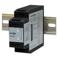
Isolation Amplifier
Manufacturer
Red Lion Controls
Specifications of IAMA3535
Supply Voltage Ac, Min
0V
Supply Voltage Dc, Min
11V
Width
3.12"
Signal Input Type
Selectable Current Or Voltage
Configuration Setup
DIP Switch
Iso-amp Mounting Type
DIN Rail
Supply Voltage Dc, Max
36V
Input Accuracy
± 0.1% Of FS
Signal Output Type
Selectable Current Or Voltage
Rohs Compliant
Yes
Lead Free Status / RoHS Status
Lead free / RoHS Compliant


CHECKSUM ERRORS
checksum error occurs, the LEDs will indicate where the error occurred
according to Table 1, LED Indications. Operation with a checksum error is not
recommended but can be done in critical situations. If an error occurs,
re-calibration of the field or factory ranges to be used must be performed.
If a factory checksum occurs, the IAMA will operate only in a previously
calibrated field mode. Do not perform a field scaling until the factory checksum
is cleared. Since a checksum error is a high priority LED indication, the LEDs will
indicate the error until it is cleared. This will exclude other LED information.
TABLE 1, LED INDICATIONS
GETTING STARTED
method for the Output (3 or 4 below) should be configured.
1. FACTORY preprogrammed settings for the Input, see Section 1.0
2. FIELD scaling method for the Input, see Section 2.0
3. FACTORY preprogrammed setting for the Output, see Section 3.0
4. FIELD scaling method for the Output, see Section 4.0
Note: The ranges should only be changed while power is removed from the IAMA.
TABLE 2, OUTPUT RANGE SETTINGS
TABLE 3, INPUT RANGE SETTINGS
A checksum is performed every time power is applied to the IAMA. If a
If a field checksum error occurs, the IAMA will operate only in factory mode.
One method for the Input (1 or 2 below) should be configured, and one
User Factory Calibration Fast Flash for 2 sec Off
Normal Operation
Scaling Mode
Under Range
Over Range
Invalid Range
Illegal Range Change
Factory Checksum
Field Checksum
Note: DIP switch settings
CURRENT
VOLTAGE
INPUT
INPUT
CONDITION
Note: DIP switch settings
OUTPUTS
CURRENT
OUTPUTS
VOLTAGE
0 - 100 mV
0 - 200 mV
0 - 500 mV
0 - 100 mA
0 - 20 mV
0 - 50 mV
0 - 10 mA
4 - 20 mA
0 - 20 mA
0 - 50 mA
0 - 100 V
0 - 1 mA
0 - 2 mA
0 - 5 mA
RANGE
0 - 10 V
0 - 20 V
0 - 50 V
0 - 1 V
0 - 2 V
1 - 5 V
0 - 5 V
On
Alternate with Red
Off
Off
Off
Off
Off
On, short off
4 - 20 mA
0 - 20 mA
OUTPUT
0 - 1 mA
RANGE
0 - 10 V
0 - 5 V
GREEN LED
0 = OFF
0
0
0
0
0
0
0
0
0
0
0
0
0
0
0
0
1
1
1
1
1
6
RANGE DIP SWITCHES
0 = OFF
0
0
0
0
0
0
0
0
1
1
1
1
1
1
1
1
0
0
0
0
0
7
3
0
0
0
0
1
RANGE DIP
1 = ON
SWITCHES
8
0
0
0
0
1
1
1
1
0
0
0
0
1
1
1
1
0
0
0
0
1
Slow Flash (0.8 sec rate)
Off
Alternate with Green
Fast Flash (0.4 sec rate)
On
On
On, short off
Off
4
0
0
1
1
0
1 = ON
9
0
0
1
1
0
0
1
1
0
0
1
1
0
0
1
1
0
0
1
1
0
5
0
1
0
1
0
RED LED
10
0
1
0
1
0
1
0
1
0
1
0
1
0
1
0
1
0
1
0
1
0
3
FIELD OR FACTORY MODE SELECTION
SELECTING FIELD MODE (2 Methods):
1. Scale the input or output according to SCALING PROCEDURE 2.0 or 4.0
2. Before applying power, set the input or output (or both) field/factory switch
SELECTING FACTORY MODE (2 Methods):
1. Before applying power to the IAMA set the input or output (or both) field/
2. While power is applied to the IAMA and it is operating in the field input and/
EMC INSTALLATION GUIDELINES
Interference (EMI), proper installation and wiring methods must be followed to
ensure compatibility in each application. The type of the electrical noise, source
or coupling method into the unit may be different for various installations. Cable
length, routing, and shield termination are very important and can mean the
difference between a successful or troublesome installation.
industrial environment.
1. Use shielded (screened) cables for all Signal and Control inputs. The shield
2. Never run Signal or Control cables in the same conduit or raceway with AC
3. Signal or Control cables within an enclosure should be routed as far away as
4. In extremely high EMI environments, the use of external EMI suppression
5. Long cable runs are more susceptible to EMI pickup than short cable runs.
WIRING CONNECTIONS
Also cabling should conform to appropriate standards of good installation, local
codes and regulations. It is recommended that power supplied to the unit be
protected by a fuse or circuit breaker. When wiring the unit, use the numbers on
the label to identify the position number with the proper function. Strip the wire,
leaving approximately 1/4" (6 mm) of bare wire exposed. Insert the wire into
the terminal, and tighten the screw until the wire is clamped tightly.
to the up (field) position. Field calibration values will be restored upon
power-up. If the IAMA has not been previously field calibrated, the E
will contain the factory calibration values which will be restored.
factory switch to the down (factory) position. Factory calibration values will
be restored upon power-up.
or output mode, set the desired field/factory switch(s) to the down (factory)
position. The factory calibration values will be restored.
Although this unit is designed with a high degree of immunity to ElectroMagnetic
Listed below are some EMC guidelines for successful installation in an
(screen) pigtail connection should be made as short as possible. The
connection point for the shield depends somewhat upon the application.
Listed below are the recommended methods of connecting the shield, in order
of their effectiveness.
a. Connect the shield only at the rail where the unit is mounted to earth
b. Connect the shield to earth ground at both ends of the cable, usually when
c. Connect the shield to common of the unit and leave the other end of the
power lines, conductors feeding motors, solenoids, SCR controls, and
heaters, etc. The cables should be run in metal conduit that is properly
grounded. This is especially useful in applications where cable runs are long
and portable two-way radios are used in close proximity or if the installation
is near a commercial radio transmitter.
possible from contactors, control relays, transformers, and other noisy
components.
devices, such as ferrite suppression cores, is effective. Install them on Signal
and Control cables as close to the unit as possible. Loop the cable through the
core several times or use multiple cores on each cable for additional protection.
Install line filters on the power input cable to the unit to suppress power line
interference. Install them near the power entry point of the enclosure. The
following EMI suppression devices (or equivalent) are recommended:
Therefore, keep cable runs as short as possible.
All conductors should meet voltage and current ratings for each terminal.
ground (protective earth).
the noise source frequency is above 1 MHz.
shield unconnected and insulated from earth ground.
Ferrite Suppression Cores for signal and control cables:
Line Filters for input power cables:
Note: Reference manufacturer’s instructions when installing a line filter.
Fair-Rite # 0443167251 (RLC #FCOR0000)
TDK # ZCAT3035-1330A
Steward #28B2029-0A0
Schaffner # FN610-1/07 (RLC #LFIL0000)
Schaffner # FN670-1.8/07
Corcom #1VR3
2
PROM
Related parts for IAMA3535
Image
Part Number
Description
Manufacturer
Datasheet
Request
R

Part Number:
Description:
Counter
Manufacturer:
Red Lion Controls
Datasheet:
Part Number:
Description:
Miniature Length Sensor
Manufacturer:
Red Lion Controls
Datasheet:
Part Number:
Description:
Model Lsc - Single Channel Output Length Sensor
Manufacturer:
Red Lion Controls
Datasheet: