G4BRICKBASE OPTO 22, G4BRICKBASE Datasheet - Page 22
G4BRICKBASE
Manufacturer Part Number
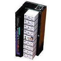
G4BRICKBASE
Description
Programmable Logic Controller
Manufacturer
OPTO 22
Datasheet
1.G4BRICKBASE.pdf
(37 pages)
Specifications of G4BRICKBASE
Leaded Process Compatible
No
Peak Reflow Compatible (260 C)
No
For Use With
I/O Bricks
Lead Free Status / RoHS Status
Contains lead / RoHS non-compliant


Copyright © 2000 Opto 22. All rights reserved. All trademarks, trade names, logos, and service marks referenced herein belong to their respective companies.
Form 859-000511
The circuit diagram illustrates a typical 1 Ø motor winding inductance and the phase shift
capacitor can cause twice line voltage to appear across the open SSR. A 240-volt SSR should
be used for a 120-Volt line. During the transition period when one SSR is turned on and the
other SSR is going off, both SSRs may be on. In this case, the capacitor may discharge through
the two SSRs, causing large currents to flow, which may destroy the SSRs. The addition of RL
as shown will protect the SSRs from the short circuit capacitor discharge current.
Three-phase motors may
be controlled by solid-state
relays as shown. A third
SSR as shown is optional,
but not necessary. The
control windings may be
connected in series or
parallel. Care should be
taken to ensure that surge
current drawn by the motor
does not exceed surge
current rating of the SSR.
CALCULATE RL as: RL =
EXAMPLE: 10 amp SSR
120 V AC Line
RL =
10 x SSR full load rating
1.4 x 120
10 x 10
q q q q q
q q q q q
1.4 EAC
= 1.7 ohm
Three-phase reversing motor control can be implemented with four
SSRs as shown in the connection diagram. The SSRs work in pairs
with SSR1 and SSR3 operated for rotation in one direction and SSR2
and SSR4 operated for rotation in the reverse direction. The resistor
R1 as shown in the connection diagram protects against line-to-line
shorts if SSR1 and SSR4 or SSR3 and SSR2 are on at the same time
during the reversing transition period. Use the following table as a
guide to the proper selection of an SSR for this application.
The resistors are unnecessary if the
control circuit is designed to ensure
one SSR is off before the other SSR
is on.
page 13/13
Related parts for G4BRICKBASE
Image
Part Number
Description
Manufacturer
Datasheet
Request
R

Part Number:
Description:
SSR, PANEL MOUNT, 280VAC, 32VDC, 10A
Manufacturer:
OPTO 22
Datasheet:

Part Number:
Description:
SSR, PANEL MOUNT, 280VAC, 32VDC, 25A
Manufacturer:
OPTO 22
Datasheet:
Part Number:
Description:
SSR, PANEL MOUNT, 280VAC, 32VDC, 25A
Manufacturer:
OPTO 22
Datasheet:
Part Number:
Description:
SSR, PANEL MOUNT, 280VAC, 32VDC, 45A
Manufacturer:
OPTO 22
Datasheet:
Part Number:
Description:
SSR, PANEL MOUNT, 280VAC, 32VDC, 45A
Manufacturer:
OPTO 22
Datasheet:

Part Number:
Description:
SSR, 10A, 240VAC
Manufacturer:
OPTO 22
Datasheet:

Part Number:
Description:
Programmable Logic Controller
Manufacturer:
OPTO 22
Datasheet:

Part Number:
Description:
Programmable Logic Controller
Manufacturer:
OPTO 22
Datasheet:

Part Number:
Description:
Solid State Relays, Accessories
Manufacturer:
OPTO 22
Datasheet:
