G4BRICKBASE OPTO 22, G4BRICKBASE Datasheet - Page 19
G4BRICKBASE
Manufacturer Part Number
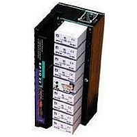
G4BRICKBASE
Description
Programmable Logic Controller
Manufacturer
OPTO 22
Datasheet
1.G4BRICKBASE.pdf
(37 pages)
Specifications of G4BRICKBASE
Leaded Process Compatible
No
Peak Reflow Compatible (260 C)
No
For Use With
I/O Bricks
Lead Free Status / RoHS Status
Contains lead / RoHS non-compliant


Like all semiconductor devices, SSR current ratings
must be based on maximum junction temperature.
All Opto 22 SSRs operate conservatively at
maximum junction temperatures of 110° C.
Determining an adequate heat sink for a given
SSR conducting a given current is very simple.
Note: Thermally conductive grease must be used
between the relay base and the heat sink.
Form 859-000511
120-Volt, 20-Amp Load
50° C Ambient Air
Choose Model 120D25 SSR.
Calculate dissipation as: 20 amps x 1.3 Watts per amp = 26 Watts
Calculate temperature rise junction to SSR base as: 26 Watts x 1.2° C per Watt = 31.2° C
Calculate allowable temperature of heat sink by subtracting 31.2° C from 110° C allowable junction temperature:
The heat sink is in a 50°C ambient, therefore, allowable temperature rise on heat sink is: 78.8° C-50° C = 28.8° C
If heat sink is allowed to rise 28.8° C above ambient, then the thermal resistance of the heat sink is simply the 28.8° C rise divided by
the 26 Watt. Any heat sink having a thermal resistance less than 1.1° C per Watt will be adequate.
When solid-state relays are operated in an on/off mode, it may be advantageous to calculate the RMS value of the current through the
SSR for heat sinking or determining the proper current rating of the SSR for the given application.
I
T
T
I
RMS
ON
1
2
= Time current is on
= Time current is off
= RMS value of load current during on period
= RMS value of load or SSR
110° C-31.2 = 78.8° C
I
RMS
=
(I
ON
T
1
)
+ T
2
x T
2
1
page 10/13
Related parts for G4BRICKBASE
Image
Part Number
Description
Manufacturer
Datasheet
Request
R

Part Number:
Description:
SSR, PANEL MOUNT, 280VAC, 32VDC, 10A
Manufacturer:
OPTO 22
Datasheet:

Part Number:
Description:
SSR, PANEL MOUNT, 280VAC, 32VDC, 25A
Manufacturer:
OPTO 22
Datasheet:
Part Number:
Description:
SSR, PANEL MOUNT, 280VAC, 32VDC, 25A
Manufacturer:
OPTO 22
Datasheet:
Part Number:
Description:
SSR, PANEL MOUNT, 280VAC, 32VDC, 45A
Manufacturer:
OPTO 22
Datasheet:
Part Number:
Description:
SSR, PANEL MOUNT, 280VAC, 32VDC, 45A
Manufacturer:
OPTO 22
Datasheet:

Part Number:
Description:
SSR, 10A, 240VAC
Manufacturer:
OPTO 22
Datasheet:

Part Number:
Description:
Programmable Logic Controller
Manufacturer:
OPTO 22
Datasheet:

Part Number:
Description:
Programmable Logic Controller
Manufacturer:
OPTO 22
Datasheet:

Part Number:
Description:
Solid State Relays, Accessories
Manufacturer:
OPTO 22
Datasheet:
