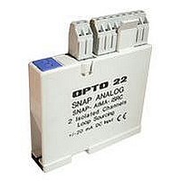
SNAP-AIPM OPTO 22, SNAP-AIPM Datasheet - Page 2

SNAP-AIPM
Manufacturer Part Number
SNAP-AIPM
Description
Power Monitoring Module
Manufacturer
OPTO 22
Type
Inputr
Specifications of SNAP-AIPM
Accessory Type
Single-phase Power Monitoring Module
Leaded Process Compatible
No
Peak Reflow Compatible (260 C)
No
Signal Input Type
85 To 250V And 0 To 10A RMS
Brand/series
SNAP Series
Connection To Host
Backplane
Current, Input
100 mA
Current, Supply
0 to 10 A
Dimensions
82.55mmL×18.29mmW×90.17mmH
Input
85 to 250/0 to 10 VAC/AAC
Input Resolution
10 mV
Input Type
Analog
Input, Range
85 to 250/0 to 10 VAC/AAC
Mounting Type
PCB
Number Of Channels
2
Number Of Inputs
2 Channels
Primary Type
Control
Resistance, Input
1 Megohms
Special Features
Transformer Isolation, Optical Isolation
Standards
UL, CSA, CE Certified
Temperature, Operating
0 to +70 °C
Voltage, Isolation
4000 V
Voltage, Supply
5 VDC
No. Of Analog Inputs
4
Resolution
10mV, 400uA
Rohs Compliant
No
For Use With
Snap I/O Modules
Lead Free Status / RoHS Status
Contains lead / RoHS non-compliant
PAGE
2
The SNAP-AIPM module offers four channels (points) of data,
two from wired inputs and two calculated by the module:
To calculate power factor, simply use the data in points 2 and 3
in the formula: Power Factor = (True Power Magnitude)/ (volt-
amps).
SNAP-AIPM-3
The SNAP-AIPM-3 provides 14 channels of data, some from
wired inputs and some calculated by the module. For each of
the three phases, the module includes the same four channels
as in the SNAP-AIPM (see previous page); in addition, it
includes two summation values. Calculations occur within the
module and are available to the SNAP PAC brain or rack-
mounted controller. All channels are shown in the table below.
CTs must be used for current inputs. Potential transformers are
required for voltage inputs when voltage exceeds 300 VAC.
Required: Brain firmware 9.1b and PAC Project 9.1a or newer.
Data Channels for SNAP-AIPM-3
Opto 22 • 43044 Business Park Drive • Temecula, CA 92590-3614 • www.opto22.com
SALES 800-321-6786 • 951-695-3000 • FAX 951-695-3095 • sales@opto22.com • SUPPORT 800-835-6786 • 951-695-3080 • FAX 951-695-3017 • support@opto22.com
© 2006–2011 Opto 22. All rights reserved. Dimensions and specifications are subject to change. Brand or product names used herein are trademarks or registered trademarks of their respective companies or organizations.
Pt Data
0
1
2
3
Pt Data
0
1
2
3
4
5
6
7
8
9
10 True Power
11 Volt-Amps
12
13
0–250 AC VRMS Measured from VRMS input
0–10 AC ARMS
True Power
Volt-Amps
0–300 AC VRMS Phase A: Measured from VRMS input
0–5 AC ARMS
True Power
Volt-Amps
0–300 AC VRMS Phase B: Measured from VRMS input
0–5 AC ARMS
True Power
Volt-Amps
0–300 AC VRMS Phase C: Measured from VRMS input
0–5 AC ARMS
1-second energy
sum
1-second abs
energy sum
Data Source
Phase A, from ARMS input
Phase A: Calculated from synchro-
nous measurement of volts and amps
Phase A: Calculated (VRMS x ARMS)
Phase B, from ARMS input
Phase B: Calculated from synchro-
nous measurement of volts and amps
Phase B: Calculated (VRMS x ARMS)
Phase C, from ARMS input
Phase C: Calculated from synchro-
nous measurement of volts and amps
Phase C: Calculated (VRMS x ARMS)
True Power sum ABC (signed)
True Power sum of absolute value of
each A, B, and C (always positive)
Data Source
Measured from ARMS input
Calculated from synchronous mea-
surement of volts and amps
Calculated (VRMS x ARMS)
SNAP Power Monitoring Modules
SNAP-AIPM-3V
The SNAP-AIPM-3V also provides 14 channels of data, some
from wired inputs and some calculated by the module. All
channels are shown in the table below.
The SNAP-AIPM-3V requires CTs with a 0.333 VAC secondary.
These CTs are safer and less expensive than the CTs used with
the SNAP-AIPM-3. See the
Sheet
Required: Brain firmware 9.1b and PAC Project 9.1a or newer.
Data Channels for SNAP-AIPM-3V
Isolation
All SNAP analog input modules, including the SNAP-AIPM,
SNAP-AIPM-3, and SNAP-AIPM-3V, are transformer isolated as
well as optically isolated from all other modules and from the
SNAP PAC brain or rack-mounted controller.
Optical isolation provides 4,000 volts of transient (4,000 V for 1
ms) protection for sensitive control electronics from industrial
field signals. Transformer isolation prevents ground loop cur-
rents from flowing between field devices and causing noise
that produces erroneous readings. Ground loop currents are
caused when two grounded field devices share a connection,
and the ground potential at each device is different.
However, note that the input points on the modules in this
data sheet are not isolated from each other. Because they
share the same reference terminal, polarity must be observed.
Pt Data
0
1
2
3
4
5
6
7
8
9
10 True Power
11 Volt-Amps
12
13
0–300 AC VRMS Phase A: Measured from VRMS input
0–0.333 VAC
True Power
Volt-Amps
0–300 AC VRMS Phase B: Measured from VRMS input
0–0.333 VAC
True Power
Volt-Amps
0–300 AC VRMS Phase C: Measured from VRMS input
0–0.333 VAC
1-second energy
sum
1-second abs
energy sum
(form 1938) for suitable CTs available through Opto 22.
Data Source
Phase A, from ARMS input
Phase A: Calculated from synchro-
nous measurement of volts and amps
Phase A: Calculated (VRMS x ARMS)
Phase B, from ARMS input
Phase B: Calculated from synchro-
nous measurement of volts and amps
Phase B: Calculated (VRMS x ARMS)
Phase C, from ARMS input
Phase C: Calculated from synchro-
nous measurement of volts and amps
Phase C: Calculated (VRMS x ARMS)
True Power sum ABC (signed)
True Power sum of absolute value of
each A, B, and C (always positive)
Split-Core Current Transformers Data


