SNAP-AIPM OPTO 22, SNAP-AIPM Datasheet - Page 16
SNAP-AIPM
Manufacturer Part Number
SNAP-AIPM
Description
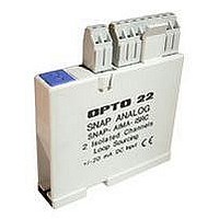
Power Monitoring Module
Manufacturer
OPTO 22
Type
Inputr
Specifications of SNAP-AIPM
Accessory Type
Single-phase Power Monitoring Module
Leaded Process Compatible
No
Peak Reflow Compatible (260 C)
No
Signal Input Type
85 To 250V And 0 To 10A RMS
Brand/series
SNAP Series
Connection To Host
Backplane
Current, Input
100 mA
Current, Supply
0 to 10 A
Dimensions
82.55mmL×18.29mmW×90.17mmH
Input
85 to 250/0 to 10 VAC/AAC
Input Resolution
10 mV
Input Type
Analog
Input, Range
85 to 250/0 to 10 VAC/AAC
Mounting Type
PCB
Number Of Channels
2
Number Of Inputs
2 Channels
Primary Type
Control
Resistance, Input
1 Megohms
Special Features
Transformer Isolation, Optical Isolation
Standards
UL, CSA, CE Certified
Temperature, Operating
0 to +70 °C
Voltage, Isolation
4000 V
Voltage, Supply
5 VDC
No. Of Analog Inputs
4
Resolution
10mV, 400uA
Rohs Compliant
No
For Use With
Snap I/O Modules
Lead Free Status / RoHS Status
Contains lead / RoHS non-compliant


PAGE
16
Wiring Diagrams—SNAP-AIPM-3V
Opto 22 • 43044 Business Park Drive • Temecula, CA 92590-3614 • www.opto22.com
SALES 800-321-6786 • 951-695-3000 • FAX 951-695-3095 • sales@opto22.com • SUPPORT 800-835-6786 • 951-695-3080 • FAX 951-695-3017 • support@opto22.com
© 2006–2011 Opto 22. All rights reserved. Dimensions and specifications are subject to change. Brand or product names used herein are trademarks or registered trademarks of their respective companies or organizations.
Three-Phase Wiring to SNAP-AIPM-3V Module
NOTE: This wiring method is less expensive than the one on
page 13
CAUTION: Be very careful when connecting input channels.
Do not connect line voltage to the current input
channel; such a connection will result in severe damage to
the module. This damage is not covered by warranty. Use a
current transformer instead. Identical CTs must be used on all
phases.
NOTE Voltage change: Older SNAP-AIPM-3 modules had an input range
of 0–250 volts. Before wiring, check printed specs on the module.
Using this wiring, after you scale the module, the following measurements are available.
All measurements are synchronously updated every second:
Suitable current transformers (CTs) for use with the SNAP-AIPM-3V are available from
Opto 22. See form #1938, the
information.
• Volts, phase A to phase C
• Volts, phase B to phase C
but does not provide as much information.
Split-Core Current Transformers Data
• 3-phase sum of 1 sec.—signed energy (watt seconds)
• 3-phase sum of 1 sec.—unsigned energy (watt secs)
SNAP Power Monitoring Modules
Sheet, for more
CAUTION: Use caution when selecting wire gauges for your
application. Use conservative wire gauges with proper volt-
age ratings.
CAUTION: Terminals 2 and 3 share a common connection
inside the module. Make sure you observe polarity when
connecting the second channel. To avoid a potentially
hazardous short circuit, double-check wiring before turning
on the current to be monitored.
CAUTION: The SNAP-AIPM-3V
module does not contain a fuse.
Protect the system by adding a
fuse.
Suggested vendors
Protection fuses:
http://www.littelfuse.com
Voltage and current transformers:
http://www.crmagnetics.com
Related parts for SNAP-AIPM
Image
Part Number
Description
Manufacturer
Datasheet
Request
R

Part Number:
Description:
POWER SUPPLY, SWITCH MODE, 24V
Manufacturer:
OPTO 22
Datasheet:
Part Number:
Description:
Ethernet, I/O Brain, Rack Mount, 5.0 VDC 0.1 VDC @ 1.0 A; RS-232
Manufacturer:
OPTO 22
Datasheet:

Part Number:
Description:
Programmable Controller
Manufacturer:
OPTO 22
Datasheet:

Part Number:
Description:
Controllers
Manufacturer:
OPTO 22
Datasheet:

Part Number:
Description:
Brains; SNAP; 32-Channel; Digital Board; Pamux Protocol
Manufacturer:
OPTO 22
Datasheet:
Part Number:
Description:
Programmable Logic Controller
Manufacturer:
OPTO 22
Datasheet:

Part Number:
Description:
I/O Module
Manufacturer:
OPTO 22
Datasheet:

Part Number:
Description:
G4 DIGITAL I/O MODULE
Manufacturer:
OPTO 22
Datasheet:

Part Number:
Description:
Programmable Controller
Manufacturer:
OPTO 22
Datasheet:
Part Number:
Description:
Programmable Controller
Manufacturer:
OPTO 22
Datasheet:

Part Number:
Description:
Solid State Relays, Accessories
Manufacturer:
OPTO 22
Datasheet:
