0195316-051 VEEDER ROOT, 0195316-051 Datasheet - Page 226
0195316-051
Manufacturer Part Number
0195316-051
Description
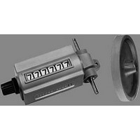
Counter Display Panel
Manufacturer
VEEDER ROOT
Datasheet
1.0195316-051.pdf
(273 pages)
Specifications of 0195316-051
No. Of Digits / Alpha
6
Digit Height
8.8mm
Lead Free Status / RoHS Status
na


D
G
T
A
L
10
I
I
O
R
A
C
C
E
S
S
E
S
I
A general purpose, form C relay module that provides high current, high
voltage load switching capability from transistor inputs. It features
contact protection, noise suppression, and easy SNAPTRACK
installation. Compatible with solid state outputs for use with MAX and
MAXjr counters. Requires 12 VDC from counter or PM41S power
supply.
■
■
■
■
■
■
■
■
Bussed relay power is provided by connectors P1 and J1. These
connectors allow multiple relay modules to be daisy chained together
and be powered by the PM41 power supply module. Electrical
connection for this relay power bus is made simply by sliding modules
together on the SNAPTRACK
Functional Diagram:
Coil connections are made thru terminal strip TB 1. Connect the output
signal of the instrument to terminal 2 “Coil.” Connect 12 VDC, ±25%, to
terminal 1 “+Vr.” Omit this connection when using the PM41 module.
Load connections are made thru terminal strip TB2. Keep loads within
the limits specified. Route all load switching conductors away from
signal lines.
10.08
Wiring Diagram:
S.P.D.T. (Form C) Configuration
M.O.V. and R-C Noise suppression
900 watt RMS rating
180 watt DC rating
Low coil power dissipation
Easy SNAPTRACK
Small size
Low cost
DYNAPAR
Digital Accessories
VEEDER-ROOT • EAGLE SIGNAL • DYNAPAR
TRANSISTOR
COIL 2
+VR 1
P1 OUTPUT POWER
+12VDC 2
COM 1
TM
installation
J1 INPUT POWER
RELAY POWER
TM
1 COM
2 +12VDC
mounting chassis.
brand
U
R
O
N
S
P
P
E
S
S
I
TB2 LOAD
1 N C
2 COM
3 N O
BLDG
GRND
Use of shielded
cable or conduit
is recommended.
LOADS
TM
PM31 Relay Module
SPECIFICATIONS
Coil:
Contacts:
Expected Life: 100,000 operations at full rated load
Termination: Terminal strip accepts #22 thru #14 AWG
Environmental:
INSTALLATION & WIRING
SNAPTRACK
lengths. (Refer to SNAPTRACK
the product catalog.) They may be trimmed by the customer for his
particular need.
Install the SNAPTRACK
provided, or with double faced tape as the application permits.
Mount the PM31 module by inserting one edge of the board into the
guide then press down on the board until it snaps into place.
Model No.
PM3100
16000700234
Package Dimensions/Specifications:
Interconnect: Terminal strips for
coil and contact connections,
.045" pin and socket connectors
for 12 V bussing for coil power.
Voltage: 12 VDC nom.
Current: 30 ma. typ.
Resistance: 400 ohms
Pickup Voltage: 9.6 VDC min.
Type: 1 SPDT (form C)
Ratings: 6.5A @ 28 VDC resistive; 7.5A @ 120 VAC resistive; 3.0A @
120 VAC tungsten
Storage Temp.: -18 to 85°C
Operating Temp.: 0 to 55° C
Humidity: 90% and non-condensing
TM
mounting chassis are available from DYNAPAR in 12"
Description
Relay Module
SNAPTRACK
TM
by using rivets or screws thru the slots
General purpose
form C relay module
TM
product information in this section of
TM
12" long
Height: 1"/25.4 mm
76.2 mm
3.0"
50.8 mm
2.0"
Related parts for 0195316-051
Image
Part Number
Description
Manufacturer
Datasheet
Request
R

Part Number:
Description:
Counter Display Panel
Manufacturer:
VEEDER ROOT
Datasheet:

Part Number:
Description:
Module; Veeder-Root Brand, A103 Series; NEMA Approved; 10 to 20 VDC
Manufacturer:
Veeder-Root
Datasheet:
Part Number:
Description:
Module; Veeder-Root Brand, A103 Series; NEMA Approved; 10 to 20 VDC
Manufacturer:
Veeder-Root
Datasheet:
Part Number:
Description:
COUNTER, VEEDER-ROOT, SQ. CASE, RAT. DR., FLANGE MOUNT, 5 FIGS., #2 ROT.
Manufacturer:
Veeder-Root
Datasheet:
Part Number:
Description:
HOUR METER, ROUND, 9-85VDC, BLADE TERMINALS, VEEDER-ROOT LOGO
Manufacturer:
Veeder-Root
Datasheet:
Part Number:
Description:
COUNTER, VEEDER-ROOT, RATCHET DRIVE, KNOB RESET, #3 ROT.
Manufacturer:
Veeder-Root
Datasheet:
Part Number:
Description:
MAX Count Series, 3 Solid State And 3 Relay Outputs
Manufacturer:
VEEDER ROOT

Part Number:
Description:
Encoder
Manufacturer:
VEEDER ROOT
Datasheet:
Part Number:
Description:
Inductive Proximity Sensor
Manufacturer:
VEEDER ROOT
Datasheet:
Part Number:
Description:
TIMER ACCESSORY, SOCKET
Manufacturer:
VEEDER ROOT
Datasheet:

Part Number:
Description:
Electromechanical Totalizing Counter
Manufacturer:
VEEDER ROOT
Datasheet:
Part Number:
Description:
Encoder, Bidirectional, Flange Mount
Manufacturer:
Veeder-Root
Datasheet: