BD40 CARLO GAVAZZI, BD40 Datasheet - Page 9
BD40
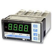
Manufacturer Part Number
BD40
Description
METER, 4DIGIT, MULTICOLOUR, UDM40
Manufacturer
CARLO GAVAZZI
Datasheet
1.BD40.pdf
(11 pages)
Specifications of BD40
Accuracy
0.1% RDG
Current Measuring Range Dc
200
Display Technology
LED
Ip/nema Rating
IP67
No. Of Characters
4
No. Of Digits / Alpha
4
Resistance Measuring Range
20 To 20k
Supply Current
5A
Svhc
No SVHC (15-Dec-2010)
Current Range Dc
200
Available stocks
Company
Part Number
Manufacturer
Quantity
Price


Programming UDM40 by means of PC
Wiring diagrams of optional modules (cont.)
Specifications are subject to change without notice
UDM40
BR SX: RS485 4-wire connection: additional devices provided with RS485 port (indicated as RS1,2,3...N) are connected
in parallel. The termination of the serial port is carried out only on the last instrument of the network. The serial module is
provided with a jumper for the termination of the RS485 network as shown in the figure above.
Note: particular types of cables or plants may require an external termination. For the network connections use twisted
cable type AWG26.
BO R4: dual relay output + dual open collector output: the load resistances (Rc) must be designed so that the close
contact current is lower than 100mA; the VDC voltage must be lower than or equal to 30VDC.
VDC: power supply output
Vo+: positive output (open collector transistor).
GND: ground collector (open collector transistor).
1
RS1,2,3...N
To UDM
To PC
2
Vcc
UDM40 is programmable by PC by means of the UdmSoft software (available on
request). The user can program all parameters of UDM40 that will be subse-
quently uploaded and set in the instrument by the RS485 network (BR SX).
Should UDM40 be without the RS485 serial module, all programming parameters
will be uploaded and set in the instrument by the RS232 auxiliary serial connec-
tion (1) located on the side of the measuring input module using the special con-
nection cable (2) available on request, as shown in the figures on the left. It is
also possible to program the instrument using the dot connector (1) by means of
the HyperTerminal Windows functions of a PC.
Note: the RS232 auxiliary port IS NOT insulated from the measuring inputs.
Ordering code of the cable (2): UCOM1
UDM40DS 040706
GND
RX
TX
SY
LED
3
2
1
5
2
3
5
9
6
1
NON terminalized network
Terminalized network
BO SY: RS232 direct
connection to PC by
means of COM port.
RS232 has no termi-
nalization.
9
Related parts for BD40
Image
Part Number
Description
Manufacturer
Datasheet
Request
R

Part Number:
Description:
MAGNETIC CYLINDRICAL PROX. SENSOR
Manufacturer:
CARLO GAVAZZI
Datasheet:
Part Number:
Description:
CYLINDRICAL MAGNETIC SENSOR
Manufacturer:
CARLO GAVAZZI
Datasheet:
Part Number:
Description:
MAGNETIC CYLINDRICAL PROX. SENSOR
Manufacturer:
CARLO GAVAZZI
Datasheet:
Part Number:
Description:
Current and Voltage Controls / Current Transformer / 3-Phase
Manufacturer:
Carlo Gavazzi
Datasheet:

Part Number:
Description:
Definite Purpose Contactor
Manufacturer:
CARLO GAVAZZI
Datasheet:
Part Number:
Description:
Definite Purpose Contactor
Manufacturer:
CARLO GAVAZZI
Datasheet: