BD40 CARLO GAVAZZI, BD40 Datasheet - Page 2
BD40
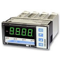
Manufacturer Part Number
BD40
Description
METER, 4DIGIT, MULTICOLOUR, UDM40
Manufacturer
CARLO GAVAZZI
Datasheet
1.BD40.pdf
(11 pages)
Specifications of BD40
Accuracy
0.1% RDG
Current Measuring Range Dc
200
Display Technology
LED
Ip/nema Rating
IP67
No. Of Characters
4
No. Of Digits / Alpha
4
Resistance Measuring Range
20 To 20k
Supply Current
5A
Svhc
No SVHC (15-Dec-2010)
Current Range Dc
200
Available stocks
Company
Part Number
Manufacturer
Quantity
Price


Additional errors
Temperature drift
Sampling rate
Display refresh time
Display
Max and min indication
Measurements
*
( )
Input specifications (cont.)
2
UDM40
Measurement accuracy, temp. drifts, max and min indications
All accuracies and min/max indications are referred to an ambient temp. range of 25°C ±5°C, rel. humidity ≤60% and scale ratio (electri-
cal/displayed scale) equal to 1. The conversion into °F is obtained acting on the electrical/displayed scale ratio.
BQ LSX/
BQ LSE/
BQ LSF
BQ HSX
BQ TRX
Thermo-
couple
Humidity
Input frequency
Magnetic field
Colour
Module
<45Hz >65Hz= ±(0.5%RDG+3DGT) 0% to 25% FS; ±(0.5%RDG+2DGT) 25% to 110% FS.
The min. indication for TRMS measurement (AC or DC) is 0; it is possible to modify the decimal point position.
-200mA to +200mA
-200mV to +200mV
-200°C to +1260°C
-328 °F to +2300°F
-200°C to +1000°C
-58 °F to +1400 °F
-328°F to +1832°F
-200µA to +200µA
-50°C to +1750°C
-200°C to +400°C
-20mA to +20mA
-58°F to +3182°F
-328°F to +752°F
-50°C to +760°C
-200V to +200V
-500V to +500V
-2mA to +2mA
-20V to +20V
-20V to +20V
-2V to +2V
-2A to +2A
-5A to +5A
Inputs
0.3% RDG, 60% to 90% R.H.
0.4% RDG, 62 to 440 Hz
0.5% RDG @ 400 A/m
See table “Measurement
accuracy, temperature drifts,
and max/min indications”
500 samples/s @ 50 Hz
200 msec @ 50Hz
4 DGT,
7 segments
height 14.2 mm
Selectable (red, amber,
green)
See table “Measurement
accuracy, temperature drifts
and max min indications”
Current, voltage, temperature
and resistance. For the cur-
rent and voltage measure-
ments: TRMS measurement
DC/AC
DC/AC
Type
K
K
E
E
S
S
J
J
T
T
DC: ±(0.1%RDG+3DGT)
TRMS (da 45 a 65Hz)*:
DC: ±(0.1%RDG+3DGT)
TRMS (45 to 65Hz)*:
±(0.2%RDG+1DGT)
±(0.2%RDG+2DGT)
±(0.2%RDG+2DGT)
±(0.2%RDG+4DGT)
±(0.2%RDG+2DGT)
±(0.2%RDG+4DGT)
±(0.2%RDG+2DGT)
±(0.2%RDG+4DGT)
±(0.2%RDG+2DGT)
±(0.2%RDG+4DGT)
0% to 25% FS;
±(0.1%RDG+2DGT)
25% to 110% FS.
±(0.3%RDG+3DGT)
0% to 25% FS;
±(0.3%RDG+2DGT)
25% to 110% FS.
±(0.1%RDG+2DGT)
±(0.3%RDG+3DGT)
±(0.3%RDG+2DGT)
0% to 25% FS;
25% to 110% FS.
0% to 25% FS;
25% to 110% FS.
Accuracy
Specifications are subject to change without notice UDM40DS 040706
Input impedance
Frequency
Overload
Compensation
Coupling type
Crest factor
RTD
TC
±150 ppm/°C
±150 ppm/°C
±150 ppm/°C
Temp. drift
Min. indication ( )
- 200°C
- 200°C
- 200°C
- 328°F
- 328°F
- 328°F
- 200.0
- 2.000
- 20.00
- 200.0
- 2.000
- 20.00
- 200.0
- 2.000
- 5.000
- 20.00
- 200.0
- 500.0
- 50°C
- 50°C
- 58°F
- 58°F
- For Pt 100-250-500-1000,
- For resistance measur. with
- For resistance measurements
Internal cold junction, within
temperature range from
0 to +50°C.
Automatic or manual com-
of distorted sine waves.
≤3; A
Direct
See table “input
impedances and overloads”
40 to 440 Hz
See table “input
impedances and overloads”
Only temperature
measurement module.
3-wire connection: up to 10Ω
20Ω range: up to max 0.1Ω
with ≥200Ωrange: up to max 10Ω
Pmax
=1.7In; V
Max. indicat. ( )
+ 1260°C
+ 1000°C
+ 1750°C
+ 1400°F
+ 2300°F
+ 1832°F
+ 3182°F
+ 760°C
+ 400°C
+ 752°F
+ 200.0
+ 2.000
+ 20.00
+ 200.0
+ 2.000
+ 20.00
+ 200.0
+ 2.000
+ 5.000
+ 20.00
+ 200.0
+ 500.0
Pmax
=1.7Un
Related parts for BD40
Image
Part Number
Description
Manufacturer
Datasheet
Request
R

Part Number:
Description:
MAGNETIC CYLINDRICAL PROX. SENSOR
Manufacturer:
CARLO GAVAZZI
Datasheet:
Part Number:
Description:
CYLINDRICAL MAGNETIC SENSOR
Manufacturer:
CARLO GAVAZZI
Datasheet:
Part Number:
Description:
MAGNETIC CYLINDRICAL PROX. SENSOR
Manufacturer:
CARLO GAVAZZI
Datasheet:
Part Number:
Description:
Current and Voltage Controls / Current Transformer / 3-Phase
Manufacturer:
Carlo Gavazzi
Datasheet:

Part Number:
Description:
Definite Purpose Contactor
Manufacturer:
CARLO GAVAZZI
Datasheet:
Part Number:
Description:
Definite Purpose Contactor
Manufacturer:
CARLO GAVAZZI
Datasheet: