TMC-IDX TRINAMIC, TMC-IDX Datasheet
TMC-IDX
Specifications of TMC-IDX


Related parts for TMC-IDX


TMC-IDX Summary of contents
Page 1
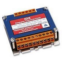
... IDX (IDX 4803 STEPPER motor controller/driver modules IDX / IDX 4803: 3.5A RMS (5A peak) / 48V IDX 7505: 5.0A RMS (7A peak) / 75V with RS485 and step-/ direction interface Trinamic Motion Control GmbH & Co – 20357 Hamburg, Germany and IDX Manual Sternstraße 67 Phone +49-40- – 0 FAX: +49-40- – ...
Page 2
... Firmware Update..................................................................................................................... 27 6.6 Option: Pseudo DC-Motor mode (not supported by software yet).......................................... 28 6.6.1 Setting up the module ........................................................................................................ 28 6.6.2 Parameterizing with RS485 ............................................................................................... 28 6.6.3 Motion Control.................................................................................................................... 28 7 Revision History ............................................................................................................................. 29 7.1 Documentation Revision ......................................................................................................... 29 7.2 Firmware Revision .................................................................................................................. 29 Copyright © 2005, TRINAMIC Motion Control GmbH & Co. KG ...
Page 3
... Table 6.7: I/Os Readout ........................................................................................................................ 21 Table 6.8: Baud rate .............................................................................................................................. 21 Table 6.9: Adjustment of Microstep Resolution..................................................................................... 22 Table 6.10: Chopper mode 3 switching velocities................................................................................. 24 Table 6.11: External signals and motor reactions ................................................................................. 25 Table 7.1: Documentation Revisions..................................................................................................... 29 Table 7.2: Firmware Revisions.............................................................................................................. 29 Copyright © 2005, TRINAMIC Motion Control GmbH & Co. KG ...
Page 4
... Features The TRINAMIC IDX is a small and rugged step / direction stepper motor driver system with a supply voltage 50V and up to 3.5A RMS motor coil current (up to 75V and RMS for IDX 7505). It can be controlled via an RS-485 interface 256 micro steps are supported for either high accuracy or high speed ...
Page 5
... Information given in this data sheet is believed to be accurate and reliable. However no responsibility is assumed for the consequences of its use nor for any infringement of patents or other rights of third parties, which may result form its use. Specifications subject to change without notice. Copyright © 2005, TRINAMIC Motion Control GmbH & Co. KG ...
Page 6
... Opto-decoupled input (negative terminal): Tie to opto-coupler negative supply voltage to disable motor driver Common 14 5…24V, Opto-coupler positive supply voltage Copyright © 2005, TRINAMIC Motion Control GmbH & Co. KG IDX Figure 3.1: Pinning of IDX Table 3.1: Power and Motor Pinning Table 3.2: Controls Pinning ...
Page 7
... Connectors Both connectors are RIA connectors. Power and motor: 6 pin connector RM 5.0 (07_06_RM5) Control: Two 4 pin and one 6 pin connectors RM 3.5, (2x 166_04_RM3.5, 1x 166_06_RM35) Copyright © 2005, TRINAMIC Motion Control GmbH & Co. KG 63.5mm 63.5mm Figure 3.2: Dimensions 63.0mm 12mm 29 ...
Page 8
... Output current on GPO (open collector) GPO T Environment temperature ENV T Temperature of case back (cooling C plate), operating Table 4.1: Operational Ratings (Orange: Different values for IDX 7505) Copyright © 2005, TRINAMIC Motion Control GmbH & Co. KG Min adjustable via frequency (actual 3.5 (optocoupler on, to input) ...
Page 9
... Table 4.2.1: Practical motor current limitations for IDX 7505 *) This limit is due to the higher current ripple in chopper mode 2, which allows a maximum of 75% to 90% of the maximum current setting not a thermal limit. Copyright © 2005, TRINAMIC Motion Control GmbH & Co. KG Maximum I RMS ...
Page 10
... Step Figure 4.1: Step, Direction and Disable Inputs Examples COM V OPTON STEP V = 20V COM V OPTON STEP Copyright © 2005, TRINAMIC Motion Control GmbH & Co. KG shall be tied to the positive supply voltage of the master and the COM OPTOFF GND undefined 1.5V undefined 16 ...
Page 11
... The minimum supply voltage has to be above two times the nominal motor voltage. ⋅ ≤ ≤ ⋅ COIL , MAX MOTOR Copyright © 2005, TRINAMIC Motion Control GmbH & Co the motor must not exceed 22-25 times the S COIL, MAX ⋅ ... and higher value would MOTOR ...
Page 12
... For further information, including a formula and description how to calculate the maximum voltage for your setup, refer to 6.2.2.3 I (RMS) COIL 3.5 A 3.0 A 2.0 A 1.0 A 0.5 A 0.3 A Table 5.1: Maximum voltage regarding motor current and inductivity Copyright © 2005, TRINAMIC Motion Control GmbH & Co (min.) V (max.) S 456 342 228 114 mH ...
Page 13
... If in doubt, please start with a lower supply voltage and check motor heating when raising the voltage. Copyright © 2005, TRINAMIC Motion Control GmbH & Co. KG 1.3 1.8 ICOIL / 48V VS = 36V VS = 24V 2 ICOIL /A 2.3 2.8 3 ...
Page 14
... Operation at very high velocities will increase the power demand up to the double value. Copyright © 2005, TRINAMIC Motion Control GmbH & Co. KG keep distance Power supply ...
Page 15
... Velocity Deceleration const. Figure 5.3: Contacts for Step-Direction The maximum step frequency is 350 kHz (limited by the opto couplers). Copyright © 2005, TRINAMIC Motion Control GmbH & Co. KG Common 5 ... 24 V Disable rotation off on GND Dir GND Step GND Acceleration TMCM-IDX PWR 12...50 V ...
Page 16
... EEPROM step/direction control is not possible until acceleration is set to zero again (and eventually stored) or the board is reset to factory default. Copyright © 2005, TRINAMIC Motion Control GmbH & Co. KG Either use a RS232 to RS485 or alternatively alternative a USB to RS485 adapter Bit rate: Data bits: Parity: none Stop bits: Flow control: none - + - + TMCM-IDX ...
Page 17
... A Reset to factory default is possible. Default address byte is “A” and default baud rate is 9600 baud. This mode can only be used with an appropriate RS485 interface. Commands are sent with a terminal program, refer 5.5. Copyright © 2005, TRINAMIC Motion Control GmbH & Co OPTOFF ...
Page 18
... Z, z Resolution max; 4: min), Refer 6.2.1.11 Examples: 1. Set chopper mode to SPI Mode ⇒ ENTER 2. Read out the actual mode Am ⇒ ENTER Copyright © 2005, TRINAMIC Motion Control GmbH & Co. KG Description Table 6.1: RS485 Commands Factory Range Default 0..2500000 0 0..100 50 ...
Page 19
... A low side Table 6.3: Failure readout in SPI mode In the other two modes the failure analysis consists of only one bit: 1: short circuit or overtemperature 0: no failure Copyright © 2005, TRINAMIC Motion Control GmbH & Co 200 (100%), AI 18 (50%), AI 45 (33%), AI 63 (25%) AC 100 18 ...
Page 20
... The bit settings are as follows: Bit Description 0: GPO is inactive (LED off GPO is active (LED on Output is changed at end of reference run Table 6.6: Output adjustment Copyright © 2005, TRINAMIC Motion Control GmbH & Co. KG Description Table 6.4: StallGuard Motor stops at 0 REF_B = 0 1 REF_A = 0 2 ...
Page 21
... set to “1” sending back of the Carriage Return character is delayed until the target velocity is reached. Example: AV –50000 ⇒ ENTER: Accelerates motor to given velocity ⇒ ENTER: Accelerates motor to velocity zero (standstill) and delays echoing of carriage return until target velocity has been reached Copyright © 2005, TRINAMIC Motion Control GmbH & Co GPI REF_B Table 6 ...
Page 22
... ⋅ COIL , MAX MOTOR It uses a chopper frequency of about 36kHz. Copyright © 2005, TRINAMIC Motion Control GmbH & Co. KG Microstep resolution SPI the motor must not exceed 22-25 times the nominal motor S and R COIL, MAX MOTOR ⋅ ... PWM Phase (default) ...
Page 23
... below 0.5, everything is OK the range 0.5 to 1.0, try operating your motor and check if motor or driver gets too hot above 1.0, choose one of the other chopper modes. See also 5.1.1.3 for graphical demonstration. Copyright © 2005, TRINAMIC Motion Control GmbH & Co. KG ⋅ ... 25 ...
Page 24
... Phase mode, so possible values for Z (microstep resolution) are This mode should only be used in very special occasions and mode 3 should be preferred if a combination of high accuracy at slow movements and high speed is needed. Copyright © 2005, TRINAMIC Motion Control GmbH & Co. KG Rounds/s 2.24 2 ...
Page 25
... Description: The Direction signal changes the motors rotation from clockwise (CW) to counterclockwise (CCW) and vice versa. Function Table: GND open wire motor CW Copyright © 2005, TRINAMIC Motion Control GmbH & Co. KG Acceleration Rotate right Direction open Increase of Step wired or connected frequency ...
Page 26
... See Figure 6.4. Turn on the module and switch it off again to remove the short-circuit. All settings are now at factory default. Copyright © 2005, TRINAMIC Motion Control GmbH & Co. KG input ...
Page 27
... Firmware Update For Firmware update start the program TMCM013boot.exe contained in the IDX-Folder of your TMCTechLibCD or at www.trinamic.com: 1. Choose your RS485 connection. 2. Select your Module ID (default is A). 3. Load the new firmware file (e.g. IDX_V1.08.hex), to download from www.trinamic.com. 4. Start the update process. At the end of the update process check your firmware version with command “AX”. ...
Page 28
... Change the voltage at GPI between 7…48V. The motor will accelerate and decelerate relative to the specified zero point. Additional parameters like resolutions of microsteps can be stored in the EEPROM. Copyright © 2005, TRINAMIC Motion Control GmbH & Co. KG Figure 6.6: GPI wiring scheme mounting hole ...
Page 29
... First Release 1.08 Bug fix, new options Copyright © 2005, TRINAMIC Motion Control GmbH & Co. KG Description Full functionality for Firmware V1.05 Added limit switch to documentation StallGuard added with RS485 command ‘G’, formerly used for output setting (LED) now command ‘O’. Switched default mode to SPI. ...