TMC-IDX TRINAMIC, TMC-IDX Datasheet - Page 3
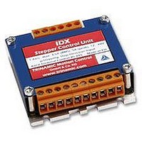
TMC-IDX
Manufacturer Part Number
TMC-IDX
Description
DRIVE, STEPPER MOTOR, 3.5A
Manufacturer
TRINAMIC
Datasheet
1.TMC-IDX.pdf
(29 pages)
Specifications of TMC-IDX
Supply Voltage Range
12VDC To 48VDC
Output Current
3.5A
Current Limit Max
5A
External Depth
23mm
External Length / Height
63mm
External Width
63mm
Load Current
3.5A
No. Of Output Channels
2
Supply
RoHS Compliant
Svhc
No SVHC (15-Dec-2010)
Rohs Compliant
Yes


IDX Manual (V1.08 / August 30th, 2006)
3
List of Figures
Figure 3.1: Pinning of IDX ....................................................................................................................... 6
Figure 3.2: Dimensions............................................................................................................................ 7
Figure 3.3: Base Plate Dimensions ......................................................................................................... 7
Figure 4.1: Step, Direction and Disable Inputs...................................................................................... 10
Figure 5.1: Maximum voltage regarding motor current and inductivity ................................................. 13
Figure 5.2: Connecting Motor and Power Supply ................................................................................. 14
Figure 5.3: Contacts for Step-Direction ................................................................................................. 15
Figure 5.4: Contacts for RS485 with an adapter ................................................................................... 16
Figure 5.5 : Connection settings for RS485 .......................................................................................... 16
Figure 6.1: GPO wiring scheme ............................................................................................................ 20
Figure 6.2: Step-Direction signals and motor reactions ........................................................................ 25
Figure 6.3: Step and Direction Signal.................................................................................................... 26
Figure 6.4: Reset to factory default ....................................................................................................... 26
Figure 6.5: Firmware update tool .......................................................................................................... 27
Figure 6.6: GPI wiring scheme .............................................................................................................. 28
Figure 6.7: Layout Changes for DC-Motor option ................................................................................. 28
List of Tables
Table 1.1: Order codes............................................................................................................................ 4
Table 3.1: Power and Motor Pinning ....................................................................................................... 6
Table 3.2: Controls Pinning ..................................................................................................................... 6
Table 4.1: Operational Ratings (Orange: Different values for IDX 7505)................................................ 8
Table 4.2.1: Practical motor current limitations for IDX 7505.................................................................. 9
Table 5.1: Maximum voltage regarding motor current and inductivity .................................................. 12
Table 6.1: RS485 Commands ............................................................................................................... 18
Table 6.2: Motor Current Examples for IDX / IDX 4803 ........................................................................ 19
Table 6.3: Failure readout in SPI mode................................................................................................. 19
Table 6.4: StallGuard............................................................................................................................. 20
Table 6.5: Limit switch ........................................................................................................................... 20
Table 6.6: Output adjustment ................................................................................................................ 20
Table 6.7: I/Os Readout ........................................................................................................................ 21
Table 6.8: Baud rate .............................................................................................................................. 21
Table 6.9: Adjustment of Microstep Resolution..................................................................................... 22
Table 6.10: Chopper mode 3 switching velocities................................................................................. 24
Table 6.11: External signals and motor reactions ................................................................................. 25
Table 7.1: Documentation Revisions..................................................................................................... 29
Table 7.2: Firmware Revisions.............................................................................................................. 29
Copyright © 2005, TRINAMIC Motion Control GmbH & Co. KG
Related parts for TMC-IDX
Image
Part Number
Description
Manufacturer
Datasheet
Request
R

Part Number:
Description:
CONTROLLER, STEPPER MOTOR, AMPLIF
Manufacturer:
TRINAMIC
Datasheet:

Part Number:
Description:
57mm/NEMA23 or 60mm/NEMA24 Stepper Motor with Controller/Driver with Encoder and Serial Interface
Manufacturer:
TRINAMIC [TRINAMIC Motion Control GmbH & Co. KG.]
Datasheet:
Part Number:
Description:
60mm/NEMA24 Stepper Motor with Controller/Driver, with Encoder and Serial Interface
Manufacturer:
TRINAMIC [TRINAMIC Motion Control GmbH & Co. KG.]
Datasheet:
Part Number:
Description:
42mm/NEMA17 Stepper Motor with Controller/Driver, Encoderand Serial Interface
Manufacturer:
TRINAMIC [TRINAMIC Motion Control GmbH & Co. KG.]
Datasheet:
Part Number:
Description:
42mm/NEMA17 High Performance BLDC Motor with Controller/Driver and Serial Interface
Manufacturer:
TRINAMIC [TRINAMIC Motion Control GmbH & Co. KG.]
Datasheet:

Part Number:
Description:
57mm diameter BLDC Encoder Motor with Controller/Driver and Serial Interface
Manufacturer:
TRINAMIC [TRINAMIC Motion Control GmbH & Co. KG.]
Datasheet:
Part Number:
Description:
57mm / NEMA23 Stepper Motor with Controller / Driver and Serial Interface
Manufacturer:
TRINAMIC [TRINAMIC Motion Control GmbH & Co. KG.]
Datasheet:
Part Number:
Description:
42mm / NEMA17 Stepper Motor with Controller / Driver and Serial Interface
Manufacturer:
TRINAMIC [TRINAMIC Motion Control GmbH & Co. KG.]
Datasheet:
