8536SBO2V02H20S SQUARE D, 8536SBO2V02H20S Datasheet - Page 22
8536SBO2V02H20S
Manufacturer Part Number
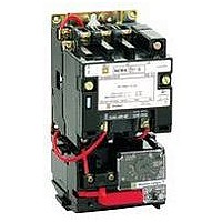
8536SBO2V02H20S
Description
Magnetic Motor Starter
Manufacturer
SQUARE D
Specifications of 8536SBO2V02H20S
No. Of Phases
Three
Power Rating
5hp
Current Rating
18A
Peak Reflow Compatible (260 C)
No
Supply Voltage Max
460VAC
Control Voltage Max
120V
Leaded Process Compatible
No
Switch Function
3PST
Current, Rating
18 A
Enclosure Type
Open
Horse Power Rating
3 @ 230 VAC, 5 @ 480 VAC
Relay Type
Contactor
Standards
UL Listed File E78351 CCN NLDX - CSA Certified File LR60905 Class 3211 04
Voltage, Coil
24 VAC
Supply Voltage Range
110VAC To 120VAC
Rohs Compliant
No
Contact Rating
18A
Lead Free Status / RoHS Status
Contains lead / RoHS non-compliant


NEMA Type 7 & 9 Enclosures for Hazardous Locations
Sizes 0-2, Bolted Cover, Cast Iron, Sizes 0-5, Bolted Cover, Cast Aluminum, Sizes 0-5, SPIN TOP
Figure 12 Size 0 and 1
NEMA 7 & 9 Bolted Cover, Cast Iron
NEMA 7 & 9 SPIN TOP
NEMA 7 & 9 Bolted Cover, Cast Aluminum
(1) 3/4 - 14 Pipe Tap
NEMA
Size
0-1
2
3-4
5
t
j
NEMA
Size
0, 1
2
NEMA
Size
0-1
2
3-4
5
Mounting
Optional
at Bottom Std.
Without control transformer.
With control transformer (Form F4T)
2.40
.63
12.70
5/98
16
Type
SBR
SCR
SER
SFR
SGR
SDR
61
323
Type
SBT
SCT
SDT
SET
SFT
SGT
Type
SBT
SCT
SDT
Dimensions — Inches/mm
A
10.63
270
12.00
305
16.13
410
20.75
527
11.00
Dimensions — Inches/mm
G
IN
14.25
13.63
18.13
24.50
9.25
279
235
8.25
4.90
Dimensions — Inches/mm
A
See Figure 12
See Figure 13
210
125
9.75
248
Bt
25.06
637
29.31
744
37.50
953
62.13
1578
mm
362
346
461
622
(1) 1 - 11 1/2 Pipe Tap
at Bottom Std.
B
7.90
201
(4)
Bj
30.06
764
34.31
871
40.50
1029
62.13
1578
®
12.00
(1) 1-11 1/2 Pipe Tap
.42
at Top Std.
H
IN
17.25
27.63
13.63
45.63
305
10
Enclosure – Figure 14
Figure 15
13.25
.63
Mounting for 4 Bolts
16
Dia. Mounting Holes
337
C
Ct
34.69
881
42.81
1087
60.00
1524
103.63
2632
mm
438
702
346
1159
V U
S T
7.00
G
178
Cj
47.69
1211
54.81
1392
66.50
1689
103.63
2632
D
J
IN
9.50
9.50
10.00
13.75
.25
Figure 13 Size 2
(1) 3/4 - 14 Pipe Tap
D
14.69
373
16.75
425
20.25
514
25.75
654
H
Mounting
6
Optional
mm
241
241
254
349
E
at Bottom Std.
Approximate Dimensions, Shipping Weights – Class 8502, 8536
2.40
.63
14.44
16
Et
6.25
159
6.75
171
8.63
219
24.13
613
61
367
P
© 1998 Square D All Rights Reserved
J
K
IN
12.25
12.25
16.25
22.50
F
O
Ej
11.25
286
11.75
298
11.63
295
24.13
613
12.00
10.25
N
305
260
R
9.25
5.88
mm
311
311
413
572
235
149
L
10.75
273
G
F
7.69
195
7.69
195
8.63
219
13.88
353
L
IN
8.88
19.25
19.25
27.50
(1) 1 1/2 - 11 1/2 Pipe Tap
at Bottom Std.
9.63
245
(4)
G
11.13
283
14.75
375
20.25
514
24.13
613
13.75
H
(1) 1-11 1/2 Pipe Tap
.42
at Top Std.
349
10
15.00
226
489
489
699
.63
mm
16
Dia. Mounting Holes
381
K
Ht
2.00
51
3.00
76
4.50
114
20.00
508
J
N
IN
4.50
9.63
9.63
13.75
7.50
191
Hj
9.00
229
9.00
229
8.00
203
20.00
508
1/2" NPT for Breather and Drain
Circuit Breaker Handle not supplied
on Class 8502 or 8536
K
mm
114
245
245
349
Enclosure
Figure 14 Size 0-5
Tap Top and
Threaded
Overload
.25
(2) "L" Pipe
J
7.63
194
11.50
292
18.00
457
21.50
546
6
Cover
Reset
Bottom
P
IN
11.00
11.00
12.63
15.38
L
R
K
7.38
187
8.50
216
12.00
305
14.38
365
Space Required To
Remove Bottom Cover
Circuit Breaker
Operational Handle –
Combination Form Only
(Add 1.00 Inch To
Overall Width)
mm
279
279
321
391
Top View
M
L
2.06
52
2.06
52
2.63
67
4.75
121
E
Q
Q, R
IN
2.38
2.38
2.38
3.44
M
9.38
238
9.38
238
11.00
279
17.00
432
G
N
®
, Cast Aluminum
N
F
P
mm
60
60
60
87
N
5.25
133
5.25
133
5.50
140
8.00
203
Space Required
To Remove
Top Cover
B
A
P
Rear View
S, T, U, V
3.13
3.13
3.75
4.00
IN
P
1.25
32
1.50
38
2.50
64
4.00
102
J
T
R
C
D
mm
80
80
95
102
R
.38
10
.38
10
.50
13
.63
16
M
K
Mtg. Holes
and/or Slots (3)
Rear Seal
L
Wt
(Lbs)
59
75
H
Wt
(Lbs)
75
115
180
500
Wt
(Lbs)
70
100
165
195
375
S
21
Related parts for 8536SBO2V02H20S
Image
Part Number
Description
Manufacturer
Datasheet
Request
R


Part Number:
Description:
Pushbutton, Non-Illum'd Red "STOP", Momentary, 1NO-1NC, Square 30mm, 10A, 600V
Manufacturer:
SQUARE D
Datasheet:
Part Number:
Description:
CB ACCESSORY, UNDERVOLTAGE TRIP 48V DC
Manufacturer:
SQUARE D
Datasheet:
Part Number:
Description:
CB ACCESSORY, TRIP UNIT
Manufacturer:
SQUARE D
Datasheet: