SI-QS90ME BANNER ENGINEERING, SI-QS90ME Datasheet - Page 5
SI-QS90ME
Manufacturer Part Number
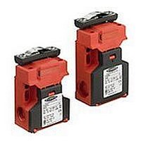
SI-QS90ME
Description
SWITCH, SAFETY INTERLOCK, 2NC, 10A
Manufacturer
BANNER ENGINEERING
Datasheet
1.SI-QS90ME.pdf
(12 pages)
Specifications of SI-QS90ME
Contact Configuration
DPST-NC
Contact Voltage Ac Max
230V
Contact Voltage Dc Max
24V
Contact Current Ac Max
10A
Contact Current Dc Max
6A
Switch Terminals
Screw
Contact Current Max
10A
Circuitry
DPST-NC


must be used for each interlock guard
to achieve control reliability or Safety
Category 4 (per ISO 1849-1, EN 954-1) of
a machine stop circuit. Use of only one
safety switch per interlock guard is not
recommended.
In addition, normally closed safety contacts
from each of the two safety switches should
be connected to the two separate inputs of a
2-channel safety module or safety interface,
as illustrated in Figure 3. This is required to
provide monitoring for safety switch contact
failure, and to provide the necessary reset
routine, as required by IEC 60204-1 and
NFPA 79 machine safety standards.
Monitoring multiple guards with a series
connection of multiple safety interlock
switches is not a Safety Category 4
Application (per ISO 1849-1, EN 954-1).
A single failure may be masked or
not detected at all. When such a
configuration is used, procedures must
be performed regularly to verify proper
operation of each switch.
Banner Engineering Corp. • Minneapolis, MN U.S.A.
www.bannerengineering.com • Tel: 763.544.3164
WARNING . . .
Connection of Safety
Interlock Switches
CAUTION . . .
Electrical Installation
Two safety switches
Machine Safety Switches –
Series
Access to the Wiring Chamber
The wiring chamber is accessed via the hinged door. See Figure 1. Select the best wiring
entrance and thread in the ½" x 14 NPT conduit adapter (supplied), or the optional M20
x 1.5 or M16 x 1.5 cable gland. The switch knockout will break loose with the final turn of
the conduit adapter or cable gland (i.e., as it bottoms out).
Connection to a Machine
As illustrated in Figure 3, a normally-closed safety contact (i.e., a safety contact that is
closed when the actuator is engaged) from each of two safety switches per interlock
guard must connect to a 2-channel safety module or safety interface in order to achieve
a control reliable interface to the master stop control elements of a machine. Examples of
appropriate safety modules include 2-channel emergency stop (E-stop) safety modules
and gate monitor safety modules.
Two functions of the safety module or safety interface are:
1. to provide a means of monitoring the contacts of both safety switches for contact
2. to provide a reset routine after closing the guard and returning the safety switch
Use only a positively driven, normally closed safety contact from each switch for
connection to the safety module. The normally open contact may be used for control
functions that are not safety-related. A typical use is to communicate with a process
controller. Refer to the installation instructions provided with the safety modules for more
information regarding the interface of the safety module to the machine stop control
elements.
Figure . Connect two redundant safety switches per interlock guard to an appropriate
failure, and to prevent the machine from restarting if either switch fails; and
contacts to their closed position. This prevents the controlled machinery from restarting
by simply reinserting the safety switch actuators. This necessary reset function is
required by ANSI B11 and NFPA 79 machine safety standards.
2-channel Gate Monitor Module, etc.)
Switch
Channel
Safety
-channel input safety module.
Input
#1
#1
(2-channel E-stop Module
2-channel Safety Module
Channel
Switch
Safety
Input
#2
#2
SI-QS75 and SI-QS90 Series Flat Pack Style
Electrical Installation
Single gate
or guard
NOTE: Refer to the installation instructions
provided with the safety module for
information regarding the interface
of the safety module to the machine
stop control elements.
P/N 49370 rev. E
5
Related parts for SI-QS90ME
Image
Part Number
Description
Manufacturer
Datasheet
Request
R

Part Number:
Description:
SI-QS-SSA-4 STANDARD ACTUATOR
Manufacturer:
BANNER ENGINEERING

Part Number:
Description:
Photoelectric Sensor
Manufacturer:
BANNER ENGINEERING
Datasheet:

Part Number:
Description:
Programmable Indicator Light
Manufacturer:
BANNER ENGINEERING
Datasheet:
Part Number:
Description:
INDICATOR LED PANEL 50MM GRN/RED/YEL 30V
Manufacturer:
BANNER ENGINEERING
Datasheet:
Part Number:
Description:
Programmable Indicator Light
Manufacturer:
BANNER ENGINEERING
Datasheet: