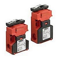
SI-QS90ME BANNER ENGINEERING, SI-QS90ME Datasheet

SI-QS90ME
Specifications of SI-QS90ME
Related parts for SI-QS90ME
SI-QS90ME Summary of contents
Page 1
... In-Line Stamped SI-QS90MFE SI-QS-SSU (Direct replacement for models Flexible SI-QS90MRHE and SI-QS90MRVE) SI-QS-SSA SI-QS90MEHF In-Line †† (High Force) Die-Cast NOTE: This symbol is used in the switching diagrams to identify the point in actuator travel where the normally closed safety contact is fully open. † ...
Page 2
... ISO 13849 (EN954-1). In addition, the user of Banner safety switches has the responsibility to ensure that all local, state, and national laws, rules, codes, and regulations relating to the use of Banner safety switches in any particular application are satisfied. Extreme care is urged that all legal requirements have been met and that all installations and maintenance instructions are followed ...
Page 3
... A kit contains an interlock and actuator. Individual interlock bodies or actuators are for replacement purposes only. See Warning on page 10. †† High Force (11.25 lbf) holding force integrated into switch. Use SI-QS-SSA In-Line Actuator only; also see accessory SI-QS-100 on page 9. Figure 1. Rotating the actuator head and accessing the wiring chamber Banner Engineering Corp. • ...
Page 4
... A switch and its actuator must never be used as a mechanical stop. Overtravel may cause damage to switch. 1. Temporarily mount the switch body in place, with its actuator inserted, using the slotted 5 mm holes. See Figure 2. NOTE: The slotted holes in the switch body must ONLY be used for alignment during installation ...
Page 5
... This prevents the controlled machinery from restarting by simply reinserting the safety switch actuators ...
Page 6
... Confirmation that the safety switch is not being used as an end stop, 4. Loosening of the switch or actuator mounting hardware, and 5. Verification that it is not possible to reach any hazard point through an opened guard (or any opening) before hazardous machine motion has completely stopped. In addition, a qualified person should check for the following on a periodic schedule ...
Page 7
... SI-QS90 models: 0.13 kg (0.29 lb) Application Notes Models with one and two contacts have three cable entry locations (bottom and two sides); models with three contacts have two cable entry locations (two sides). All entry locations are sealed with knockouts. To remove knockouts, thread the supplied M16 x 1.5 or M20 x 1.5 to ½"–14 NPT conduit adapter or optional M16 x 1 ...
Page 8
... Side View of Actuator Side View of Actuator 8 P/N 49370 rev. E SI-QS75 and SI-QS90 Series Flat Pack Style Dimensions Model SI-QS75.. Interlock Body Front View 90.0 mm 75.0 mm (3.55") (2.95") 17.5 mm M16 x 1.5 (0.06") 52.0 mm (2.07") Model SI-QS-SSA-4 In-line Actuator 40 ...
Page 9
... NPT M20 x 1.5 SI-QS90 to ½"-14 NPT Conduit Adapters High-force accessory for in-line actuator SI-QS-SSA. Provides additional holding force for particularly heavy doors, gates, or guards. Adjustable from 50 to 100 Newtons (force). Used only for switches with in-line actuator SI-QS-SSA. Dimensions 34.0 mm 19.0 mm (1.34" ...
Page 10
... The actuator is stamped steel. For hinged doors with a radius (2") or greater. Flexes in four directions. The actuator is die-cast stainless steel. Clear acrylic adapter plate used to retrofit SI-QS-SSU to older flexible actuators SI-QS-HMA and SI-QS-VMA. Application Banner Engineering Corp. • Minneapolis, MN U.S.A. ...
Page 11
... Machine Safety Switches – Banner Engineering Corp. • Minneapolis, MN U.S.A. www.bannerengineering.com • Tel: 763.544.3164 SI-QS75 and SI-QS90 Series Flat Pack Style 11 P/N 49370 rev. E ...
Page 12
... Banner products. This warranty is in lieu of any other warranty either expressed or implied. P/N 49370 rev. E Banner Engineering Corp., 9714 Tenth Ave. No., Minneapolis, MN USA 55441 • Phone: 763.544.3164 • www.bannerengineering.com • Email: sensors@bannerengineering.com SI-QS75 and SI-QS90 Series Flat Pack Style ® ...


