E5CSVR1TD500ACDC24V Omron, E5CSVR1TD500ACDC24V Datasheet - Page 8
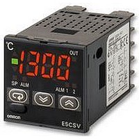
E5CSVR1TD500ACDC24V
Manufacturer Part Number
E5CSVR1TD500ACDC24V
Description
TEMPERATURE CONTROLLER, RELAY OP
Manufacturer
Omron
Datasheet
1.E5CSVQ1T500AC100240V.pdf
(20 pages)
Specifications of E5CSVR1TD500ACDC24V
Thermocouple Type
T
Operating Temperature Max
55°C
Operating Temperature Min
-10°C
Output Voltage Max
250VAC
Svhc
No SVHC (15-Dec-2010)
Accuracy
± 0.5%
Approval Bodies
CE, CRUus
Colour
Black
Lead Free Status / RoHS Status
Lead free / RoHS Compliant


2. Operation Settings
Use the control mode switches (
control mode. (All switches are OFF for the default settings.)
Note: The previous name Pt100 has been changed to JPt100 in
For details on the position of the temperature range switch, control mode switches, and alarm mode switch, refer to page 6.
8
Note: Turn OFF the power before changing the DIP switch settings on the E5CSV. Each of the switch settings will be enabled after the power is
ON/OFF
PID
Control
period
Direct/
reverse
opera-
tion
Input
shift
display
Tempera-
ture
Sensor
selection
Temper-
ature
unit
accordance with revisions to JIS. The previous name J-DIN has
been changed to L in accordance with revisions to DIN
standards.
turned ON.
Function selection
PID control
ON/OFF control
2 s
20 s
Direct operation
(cooling)
Reverse operation
(heating)
Enabled
Disabled
Thermo-
couple
Platinum
resistance
thermome-
ter
Multi-input
(thermo-
couple/
platinum
resistance
thermome-
ter)
° F
° C
Temperature Controllers
K, L
K, J
Pt100
JPt100
Platinum
resis-
tance
thermom-
eter
input
Thermo-
couple
input
ON
1
OFF
ON
2
1
ON
3
1
4
OFF
ON
2
5
2
E5CSV
6
OFF
ON
) to change the
3
3
OFF
ON
4
4
OFF
OFF
OFF
ON
ON
ON
5
5
OFF
6
ON
6
3. Alarm Modes
Select the number of the alarm mode switch
the alarm mode. (The default is 2).
Note: 1. No alarm. The alarm value (alarm operation display) will not
Rising Temperature
Upper-limit
alarm
Lower-limit
alarm
Alarm
output
value
Set
0, 9
1
2
3
4
5
6
7
8
SP
OFF
ON
2. Standby Sequence Function (The standby sequence
Alarm function OFF
Upper- and lower-
limit
Upper-limit
Lower-limit
Upper- and lower-
limit range
Upper- and lower-
limit with standby
sequence (See note
2.)
Upper-limit with
standby sequence
(See note 2.)
Lower-limit with
standby sequence
(See note 2.)
Absolute-value
upper-limit
be displayed when the setting is 0 or 9 even if the selection
key is pressed.
Alarm Setting Range
X: 0 to FS (full scale); Y: Within temperature range
The value of X is the deviation setting for the SP (set point).
operates when the power is turned ON.)
Alarm type
OFF
OFF
OFF
OFF
OFF
OFF
OFF
OFF
ON
ON
ON
ON
ON
ON
ON
ON
Dropping Temperature
Alarm output operation
Upper-limit
alarm
Lower-limit
alarm
Alarm
output
SP
OFF
ON
X
OFF
X
X
X
X
SP
SP
SP
SP
SP
SP
SP
0
when changing
X
X
X
X
X
Y
Related parts for E5CSVR1TD500ACDC24V
Image
Part Number
Description
Manufacturer
Datasheet
Request
R

Part Number:
Description:
G6S-2GLow Signal Relay
Manufacturer:
Omron Corporation
Datasheet:
Part Number:
Description:
Compact, Low-cost, SSR Switching 5 to 20 A
Manufacturer:
Omron Corporation
Datasheet:
Part Number:
Description:
Manufacturer:
Omron Corporation
Datasheet:
Part Number:
Description:
Manufacturer:
Omron Corporation
Datasheet:
Part Number:
Description:
Manufacturer:
Omron Corporation
Datasheet:
Part Number:
Description:
Manufacturer:
Omron Corporation
Datasheet:
Part Number:
Description:
Manufacturer:
Omron Corporation
Datasheet:
Part Number:
Description:
Manufacturer:
Omron Corporation
Datasheet: