SNAP-IT-PM-ADS-PLUS OPTO 22, SNAP-IT-PM-ADS-PLUS Datasheet
SNAP-IT-PM-ADS-PLUS
Specifications of SNAP-IT-PM-ADS-PLUS


Related parts for SNAP-IT-PM-ADS-PLUS


SNAP-IT-PM-ADS-PLUS Summary of contents
Page 1
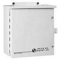
... The SNAP-IT-PM-ADS-PLUS (with an Ethernet brain) and SNAP-IT-PM-UADS-PLUS (with an Ultimate brain) come ready for a dial-up connection and include the brain, a 12-module mounting rack, a power supply, a modem, a digital input module to monitor AC power to the unit, and backup battery. • ...
Page 2
... What’s in this Guide? This brief guide shows you how to insert modules in the unit, connect power, and mount the unit. For SNAP-IT-PM-ADS, SNAP-IT-PM-ADS-PLUS, and SNAP-IT-PM-ADS-PLUS24V: To configure modules and communicate with the unit, you will also need Opto 22 form #1460, the SNAP Ethernet-Based I/O Units User’s Guide, and form #1440, the ioManager User’s Guide, which are included in this binder ...
Page 3
... If your unit contains the optional modem, you can find complete modem documentation on our Web site at www.opto22.com. Search on the word For Help If you have problems installing or using your SNAP-IT unit and cannot find the help you need in the product guides, you can contact Opto 22 Product Support. Phone: ...
Page 4
... QUICK START Quick Start The following diagrams show the parts inside the SNAP-IT panel-mount models and wiring for attaching external AC power. SNAP-IT-PM-ADS and SNAP-IT-PM-UADS SNAP-IT-PM-ADS-PLUS and SNAP-IT-PM-UADS-PLUS 4 1267-050202—SNAP-IT-PM Installation Guide External power connection External power connection ...
Page 5
... SNAP-IT-PM-ADS-PLUS24V and SNAP-IT-PM-UADS-PLUS24V About Modules Input/output (I/O) modules are sold separately from the SNAP-IT unit so you can choose the modules you need from the wide variety available. Modules come in three basic types: • Digital modules monitor and control electrical, mechanical, and electronic devices that can be in one of only two states: either on or off ...
Page 6
... Inserting Modules modules snap into place in the row of connectors inside the SNAP-IT unit. 1. Make sure all power to the SNAP-IT unit is off. Remove the small white fuse from the module mounting rack. WARNING: Make sure there is no power to the rack before continuing, or you may severely damage the module. 2. Open the unit’ ...
Page 7
... Replace the small white fuse on the module mounting rack. Mounting the Unit and Connecting Power 1. Mount the SNAP-IT-PM unit on a convenient wall or piece of equipment. 2. Inside the unit, connect external AC power to the unit as shown in the diagrams starting on page 4. 1267-050202—SNAP-IT-PM Installation Guide ...
Page 8
... For more information, see Opto 22 form #1276, the OptoGateLock Installation Guide. Using the SNAP-IT Unit on the Ethernet Network Follow instructions in the ioManager User’s Guide to assign an IP address to the SNAP-IT unit and configure I/O points and features. 8 1267-050202—SNAP-IT-PM Installation Guide ...
Page 9
... Protocols Ethernet Port Serial Port Modem Power Supply Power Consumption Temperature Humidity LED Indicators The following table describes system LEDs located on the top of the SNAP Ethernet or SNAP Ultimate brain: LED ACT Network Activity FD Full Duplex Mode ERD Ethernet—Receive Data ETD Ethernet— ...
Page 10
... Notes on Maintenance Instructions for maintenance are in the SNAP Ethernet-Based I/O Units User’s Guide. If you need to change the SNAP-IT unit’s IP address, reset it to factory defaults, or download new firmware, you will need to use instructions in the user’s guide. Copyright © 1999–2005 Opto 22. All rights reserved. Printed in the United States of America. ...