XF2M-1415-1A-R100 Omron, XF2M-1415-1A-R100 Datasheet - Page 13
XF2M-1415-1A-R100
Manufacturer Part Number
XF2M-1415-1A-R100
Description
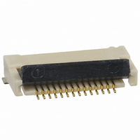
CONNECTOR FPC 14POS 0.5MM SMD
Manufacturer
Omron
Series
XF2Mr
Type
FPC Connectorr
Specifications of XF2M-1415-1A-R100
Connector Type
Top and Bottom Contacts
Number Of Positions
14
Pitch
0.020" (0.50mm)
Ffc, Fcb Thickness
0.30mm
Height Above Board
0.083" (2.10mm)
Mounting Type
Surface Mount, Right Angle
Cable End Type
Straight
Termination
Solder
Locking Feature
Rotary Lock, Backlock
Contact Finish
Gold
Contact Finish Thickness
5.9µin (0.15µm)
Operating Temperature
-30°C ~ 85°C
Current Rating
0.500A
Voltage Rating
50V
Housing Material
Liquid Crystal Polymer (LCP)
Contact Gender
SKT
Mounting Style
Surface Mount
Number Of Contact Rows
1
Number Of Contacts
14POS
Pitch (mm)
0.5mm
Body Orientation
Right Angle
Contact Resistance Max
50mOhm
Voltage Rating Max
50VDC/50VAC
Operating Temp Range
-30C to 85C
Current Rating (max)
0.5A
Housing Color
Natural
Contact Material
Copper Alloy
Contact Plating
Gold Over Nickel
Termination Method
Solder
Product Height (mm)
2mm
Product Depth (mm)
5.9mm
Product Length (mm)
11.1mm
Mounting Angle
Straight
Termination Style
Solder Pin
Lead Free Status / RoHS Status
Lead free / RoHS Compliant
Features
-
Lead Free Status / Rohs Status
Lead free / RoHS Compliant
Other names
XF2M14151AR100


Rotary Backlock Mechanism with 0.5-mm Pitch
and Low Profile of 1.1 mm
• Two models available: Ultra-slim connector with a depth
• Double-sided contacts reduce the number of parts.
• Wide molding wall on the rear bottom of the connector
• Applicable FPC thickness of 0.3 mm.
■ Ratings and Specifications
XF2W-@@15-1A/1AE
■ Dimensions
XF2W-@@15-1@
XF2W-@@15-1@E
2.1
Rated current
Rated voltage
Contact resistance
Insulation resistance 100 M Ω min. (at 250 V DC)
Withstand voltage
Insertion tolerance
Ambient operating
temperature
Rotary Backlock Connector
(0.5-mm Pitch, Double-sided Contact)
RoHS Compliant
of 3.5 mm and easy-operation connector with long
slider.
allows greater freedom in board design.
1.5
Reference pin mark
1.1
0.12
0.5
0.15
FPC insertion dimension
(See note.)
0.5 A AC/DC
50 V AC/DC
60 m Ω max. (at 20 mV max., 100 mA max.)
250 V AC for 1 min
(leakage current: 1 mA max.)
20 times
− 30 to 85 ° C (with no icing or condensation)
A
B
C
D
X
X
Slider
Contact
Hold-down clip
Housing
0.5
Hold-down
clip
soldering
0.4
Contact soldering
dimension
Pin number
indication
0.35
0.5
0.5
Applicable FPC Dimensions
±0.07
±0.03
±0.03
Note: Dotted lines refer to model XF2W-6415-1 E
X-X
Note: Dotted lines are for connectors with 64 pins.
1.2
1.8
Unlocked
H
A
±0.03
±0.05
3.4
0.8
Effective interface length
(See
note.)
1.5 min.
Two, R0.2
■ Materials and Finish
XF2W-@@15-1A/1AE
Housing
Slider
Contacts
Hold-down
Note: “E” refers to the shape and dimensions for model series XF2W-6415.
Please refer to the drawings for more information.
Table of Dimensions
Pins (See
note 2.)
(16)
16
20
24
64
2.5 min.
0.3
Locked
±0.05
3.5
XF2W-6415-1@E 31.5 33.5 34.0 32.6 31.8 33.1 33.9 32.5
XF2W-1615-1@
XF2W-2015-1@
XF2W-2415-1@
4.1
(See note 1.)
3.3
0.1
±0.05
Model
1.5 min.
LCP resin (UL94V-0)/natural
LCP resin (UL94V-0)/brown
Spring copper alloy/nickel substrate (2 μ m),
gold-plated contacts (0.15 μ m)
Spring copper alloy/fused-tin plating (2 μ m)
0.8
0.8
(See note.)
±0.05
±0.05
11.5 13.5 14.0 12.6 11.8 13.1 13.9 12.5
PCB Mating Dimensions (Top View)
7.5
9.5 11.5 12.0 10.6 9.8 11.1 11.9 10.5
A
9.5 10.0 8.6
B
0.3
0.5
±0.05
C
±0.05
E
A
XF2W
G
F
±0.05
±0.05
±0.1
±0.1
D
7.8
E
(0.125)
9.1
Pattern-prohibited
area
F
9.9
(0.15)
(0.15)
G
3.4
8.5
H
13
Related parts for XF2M-1415-1A-R100
Image
Part Number
Description
Manufacturer
Datasheet
Request
R

Part Number:
Description:
CONN FPC 14POS 0.5MM PITCH SMD
Manufacturer:
Omron
Datasheet:

Part Number:
Description:
G6S-2GLow Signal Relay
Manufacturer:
Omron Corporation
Datasheet:
Part Number:
Description:
Compact, Low-cost, SSR Switching 5 to 20 A
Manufacturer:
Omron Corporation
Datasheet:
Part Number:
Description:
Manufacturer:
Omron Corporation
Datasheet:
Part Number:
Description:
Manufacturer:
Omron Corporation
Datasheet:
Part Number:
Description:
Manufacturer:
Omron Corporation
Datasheet:
Part Number:
Description:
Manufacturer:
Omron Corporation
Datasheet:
Part Number:
Description:
Manufacturer:
Omron Corporation
Datasheet:
Part Number:
Description:
Manufacturer:
Omron Corporation
Datasheet: