E3G-MR19TG Omron, E3G-MR19TG Datasheet - Page 10
E3G-MR19TG
Manufacturer Part Number
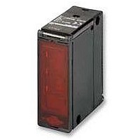
E3G-MR19TG
Description
PHOTOSWITCH, POL REFLEX, TIMED
Manufacturer
Omron
Datasheet
1.E3G-MR19G.pdf
(14 pages)
Specifications of E3G-MR19TG
Svhc
No SVHC (15-Dec-2010)
Sensing Range Max
10m
Sensor Input
Optical
Supply Voltage Ac Max
240VAC
Supply Voltage Dc Max
24VDC
Contact Voltage Ac Max
250VAC
Contact Voltage Dc Max
30VDC
Output Type
Relay
Response Time
30ms
Rohs Compliant
Yes
Dielectric Strength Vdc
2000VAC
External Depth
68mm
External Length / Height
84.95mm
External Width
29mm
Lead Free Status / RoHS Status
Lead free / RoHS Compliant


Zone teaching
Note: Perform zone teaching with the background.
Precautions
Design
Power Supply
A full-wave rectification power supply can be used with the
E3G-MR19(T)-G.
Wiring Considerations
The tensile strength of the cable during operation should not
exceed the values shown below.
● For adjustment
Display
• The following graphs indicate the status of each operation
• Set the E3G so that it will work within the stable operation
A-128
dure
Stable
operation
range
(see note)
Unstable
operation
range
(see note)
Stable
operation
range
(see note)
Note: If the operation level is set to the stable operation range, the E3G will operate with
Pro-
ce-
1
2
3
4
level.
range.
E3G-R13-G
E3G-MR19(T)-G
E3G-R17-G
the highest reliability and without being influenced by temperature change, voltage
fluctuation, dust, or setting change.
Set the mode selector to
Set the NORMAL/ZONE mode selector to
Press the
Set the mode selector to
mode.)
The teaching indicator (red) will turn ON and the teaching
indicator (green) will then turn ON.
Model
Operation
level x 1.2
Operation
level
Operation
level x 0.8
E3G-R/MR
TEACH
Stability indicator (green)
OFF
ON
ON
button with the background.
Correct Use
Tensile strength
50 N max.
10 N max.
Operation
TEACH
RUN
Operation indicator (Orange)
L · ON
OFF
ON
. (Set to L-ON or D-ON
.
D · ON
OFF
ON
ZONE
.
Maximum distance setting (in normal mode)
If you want to set the maximum distance of the sensor, set a
maximum distance as depicted in the following procedure.
Design
Power Supply
A full-wave rectification power supply can be used with the
E3G-ML79(T)-G.
Wiring Considerations
The tensile strength of the cable during operation should not
exceed the values shown below.
Miscellaneous
EEPROM Write Error
If a write error occurs (operation indicator flickers) due to pow-
er-off, static electricity or other noise in the teaching mode,
perform teaching again.
Wiring Considerations
• The cable with an external diameter of 6 to 8 mm is recom-
• Securely tighten the cover to maintain water resistance and
• Do not tighten with the cable caught by the terminal protec-
Pro-
dure
ce-
1
2
3
4
mended.
dust resistance. The thread size of the conduit socket is PG
13.5
tion cover. Otherwise, the water-resistant structure and like
cannot be maintained.
E3G-L73
E3G-ML79(T)-G
E3G-L77
Set the mode selector to
Set the NORMAL/ZONE mode selector to
Press the
When the teaching indicator (green) turns ON, the setting
is complete. Set the mode selector to
D-ON.)
The teaching indicator (red) will turn ON.
In 3 s, the teaching indicator (green) will turn ON.
Model
E3G-M#(T)-G
E3G-L/ML
TEACH
Standard Photoelectric Sensors
button 3 s or more.
Tensile strength
50 N max.
10 N max.
Operation
TEACH
.
RUN
NORMAL
. (Set to L-ON/
.
Related parts for E3G-MR19TG
Image
Part Number
Description
Manufacturer
Datasheet
Request
R

Part Number:
Description:
CONVERGENT 50mm PNP CONN.
Manufacturer:
Omron
Datasheet:
Part Number:
Description:
Photoelectric Sensors - Industrial CONVERGENT 200MM PNP CONN
Manufacturer:
Omron
Datasheet:

Part Number:
Description:
Photoelectric Sensors - Industrial NPN/PNP POL RETRORFL
Manufacturer:
Omron
Datasheet:
Part Number:
Description:
Photoelectric Sensors - Industrial CONVERGENT 2M DC CONN.
Manufacturer:
Omron
Datasheet:
Part Number:
Description:
Photoelectric Sensors - Industrial RETRO 10M AC/DC TMR. SCREW TERM
Manufacturer:
Omron
Datasheet:

Part Number:
Description:
Photoelectric Sensors - Industrial CONVERGENT 2M AC/DC SCREW TERM
Manufacturer:
Omron
Datasheet:
Part Number:
Description:
Photoelectric Sensors - Industrial RETRO 10M AC/DC SCRE W TERM.
Manufacturer:
Omron
Datasheet:
Part Number:
Description:
Photoelectric Sensors - Industrial Retro 10M DC Connector
Manufacturer:
Omron
Datasheet:
Part Number:
Description:
Photoelectric Sensors - Industrial Retro 10M DC E39-R2 not incl.
Manufacturer:
Omron
Datasheet:
Part Number:
Description:
Photoelectric Sensors - Industrial CONVERGENT 200mm NPN CONN.
Manufacturer:
Omron
Datasheet:

Part Number:
Description:
G6S-2GLow Signal Relay
Manufacturer:
Omron Corporation
Datasheet:
Part Number:
Description:
Compact, Low-cost, SSR Switching 5 to 20 A
Manufacturer:
Omron Corporation
Datasheet:
Part Number:
Description:
Manufacturer:
Omron Corporation
Datasheet: