E2EM-X8C1 2M Omron, E2EM-X8C1 2M Datasheet - Page 6
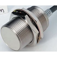
E2EM-X8C1 2M
Manufacturer Part Number
E2EM-X8C1 2M
Description
Inductive Proximity Sensor
Manufacturer
Omron
Datasheet
1.E2EM-X8X1-2M.pdf
(9 pages)
Specifications of E2EM-X8C1 2M
Sensor Input
Inductive
Sensing Range
8mm
Supply Voltage Range Dc
10V To 30V
Supply Voltage Max
30VDC
Sensing Range Max
8mm
Switch Terminals
Wire Leaded
Supply Voltage Min
10VDC
Output Type
NPN, NO
Sensor Output
NPN, NO
Rohs Compliant
Yes
Lead Free Status / RoHS Status
Lead free / RoHS Compliant


Safety Precautions
Refer to Warranty and Limitations of Liability.
This product is not designed or rated for ensuring
safety of persons either directly or indirectly.
Do not use it for such purposes.
Do not use this product under ambient conditions that exceed the
ratings.
● Design
Influence of Surrounding Metal
When mounting the Sensor within a metal panel, ensure that the
clearances given in the following table are maintained. Failure to
maintain these distances may cause deterioration in the performance
of the Sensor.
Influence of Surrounding Metal
Connecting a DC 2-wire Proximity Sensor to a PLC (Programmable Controller)
Required Conditions
Connection to a PLC is possible if the specifications of the PLC and the Proximity Sensor satisfy
the following conditions. (The meanings of the symbols are given below.)
1. The ON voltage of the PLC and the residual voltage of the Proximity Sensor must satisfy the
2. The OFF current of the PLC and the leakage current of the Proximity Sensor must satisfy the
3. The ON current of the PLC and the control output (I
Example
In this example, the above conditions are checked when the PLC Unit is the C200H-ID212, the
Proximity Sensor is the E2EM-X8X1, and the power supply voltage is 24 V.
1. V
2. I
3. I
Therefore, I
DC 2-wire
E2EM-X@X@
DC 3-wire
E2EM-X@C@
OFF
ON
following.
V
following.
I
(If the OFF current is not listed in the specifications, take it to be 1.3 mA.)
following.
I
The ON current of the PLC will vary, however, with the power supply voltage and the input
impedance, as shown in the following equation.
I
OFF
OUT
ON
ON
ON
= [V
= (V
(1.3 mA) ≥ I
(14.4 V) ≤ V
≥ I
≤ V
(min.) ≤
leak
CC
CC
CC
OUT
l
(20.4 V) − V
Type
− V
− V
Precautions for Correct Use
(min.) (3 mA) ≤ I
m
ION
R
R
leak
− V
CC
≤ I
Unshielded
Shielded
Shielded
OUT
(20.4 V) − V
(0.8 mA):
PC
)/R
R
(max.)
(5 V) − V
IN
WARNING
ON
Item
m
m
m
D
D
D
d
n
d
n
d
n
l
l
l
R
(3.8 mA):
D
(5 V) = 15.4 V: OK
PC
d dia.
(Unit: mm)
(4 V)]/R
M8
4.5
---
---
12
0
8
0
IN
M12
2.4
2.4
2.4
2.4
18
12
18
18
12
18
---
(3 kΩ) = Approx. 3.8 mA
OK
OK
OUT
l
M18
3.6
3.6
3.6
3.6
27
24
27
25
70
25
48
70
27
24
27
) of the Proximity Sensor must satisfy the
m
n
M30
120
120
45
45
45
45
45
90
45
45
45
6
6
6
6
AND/OR Connections
Error pulses and leakage current may prevent application in AND or
OR circuits. Always confirm operation in advance to confirm if there
are any problems in operation.
Mutual Interference
When installing Sensors face-to-face or side-by-side, ensure that the
minimum distances given in the following table are maintained.
Mutual Interference
DC 2-wire
E2EM-X@X@
DC 3-wire
E2EM-X@C@
Type
A
Unshield-
Shielded
Shielded
ed
(Unit: mm)
V
I
I
RIN: Input impedance of PLC (3 kΩ)
V
V
I
I
V
Values in parentheses apply to the following PLC
model and Proximity Sensor model.
PLC:
Sensor: E2EM-X8X1
ON
OFF
leak
OUT
ON
PC
R
CC
:
:
:
: OFF current of PLC (1.3 mA)
: Internal residual voltage of PLC (4 V)
: Power supply voltage (PLC: 20.4 to
: ON voltage of PLC (14.4 V)
: Control output of Proximity Sensor (3 to
Item
ON current of PLC (typ. 7 mA)
Output residual voltage of Proximity
Sensor (5 V)
Leakage current of Proximity Sensor
(0.8 mA)
100 mA)
26.4 V)
A
B
A
B
A
B
C200H-ID212
M8
---
20
15
M12
30
20
30
20
---
B
M18
200
120
60
35
60
35
E2EM
M30
110
350
300
110
90
90
6
Related parts for E2EM-X8C1 2M
Image
Part Number
Description
Manufacturer
Datasheet
Request
R

Part Number:
Description:
Proximity Sensors M18 shielded 8mm NO Xtnded rng inductive
Manufacturer:
Omron
Datasheet:
Part Number:
Description:
Proximity Sensors M12 shielded 4mm NO Xtnded rng inductive
Manufacturer:
Omron
Datasheet:
Part Number:
Description:
Proximity Sensors M30 unshlded 30mm NO Xtnded rng inductive
Manufacturer:
Omron
Datasheet:
Part Number:
Description:
Proximity Sensors 2-WIRE 15mm M30 N/O SHIELDED 2M WIRE
Manufacturer:
Omron
Datasheet:
Part Number:
Description:
Inductive Proximity Sensor
Manufacturer:
Omron
Datasheet:
Part Number:
Description:
E2EM-C30X15 W/ M12Pigtail Conn
Manufacturer:
Omron
Part Number:
Description:
Extnd M30 Shd PNP-NO 15mm M12
Manufacturer:
Omron
Datasheet:
Part Number:
Description:
EXTND M8 SHD PNP-NO 2MM M12
Manufacturer:
Omron
Datasheet:
Part Number:
Description:
Extnd M12 Shd PNP-NO 4mm M12
Manufacturer:
Omron
Datasheet:

Part Number:
Description:
Proximity Sensors M8 NPN Out 2mm 3WIRE Xtnded rng inductive
Manufacturer:
Omron
Datasheet:

Part Number:
Description:
PROXIMITY SENSOR
Manufacturer:
Omron
Datasheet:
