E2EM-X8C1 2M Omron, E2EM-X8C1 2M Datasheet - Page 2
E2EM-X8C1 2M
Manufacturer Part Number
E2EM-X8C1 2M
Description
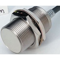
Inductive Proximity Sensor
Manufacturer
Omron
Datasheet
1.E2EM-X8X1-2M.pdf
(9 pages)
Specifications of E2EM-X8C1 2M
Sensor Input
Inductive
Sensing Range
8mm
Supply Voltage Range Dc
10V To 30V
Supply Voltage Max
30VDC
Sensing Range Max
8mm
Switch Terminals
Wire Leaded
Supply Voltage Min
10VDC
Output Type
NPN, NO
Sensor Output
NPN, NO
Rohs Compliant
Yes
Lead Free Status / RoHS Status
Lead free / RoHS Compliant


Accessories (Order Separately)
Sensor I/O Connectors (M12)
Note: Refer to Introduction to Sensor I/O Connectors for details.
Ratings and Specifications
E2EM-X@X@ DC 2-Wire Models
*1. Use the Sensor within the range in which the setting indicator (green LED) is ON (except X2 Models).
*2. The response frequency is an average value.
*3. The residual voltage is 5 V. Make sure that the device connected to the Sensor can withstand the residual voltage. (Refer to page 6 for details.)
Item
Sensing distance
Set distance *1
Differential travel
Detectable object
Standard sensing object Iron, 12 × 12 × 1 mm
Response frequency *2
Power supply voltage
(operating voltage
range)
Leakage current
Con-
trol out-
put
Indicators
Operation mode
(with sensing object
approaching)
Protection circuits
Ambient temperature
range
Ambient humidity range Operating/Storage: 35% to 95% (with no condensation)
Temperature influence
Voltage influence
Insulation resistance
Dielectric strength
Vibration resistance
Shock resistance
Degree of protection
Connection method
Weight (packed state)
Materi-
als
Accessories
Measurement conditions are as follows: standard sensing object, a distance of twice the standard sensing object, and a set distance of half the sensing distance.
Appearance
Straight
Use the XS2F-D42@-@CO-A for the E2EM-X@X1-M1J. (Terminal 3: 0 V (+V), Terminal 4: +V (0 V))
L-shape
Load current
Residual volt-
age *3
Case
Sensing sur-
face
Clamping nuts Nickel-plated brass
Toothed wash-
er
Shielded
Model
Size
Cable length
2 m
5 m
2 m
5 m
4 mm ±10%
0 to 3.2 mm
15% max. of sensing distance
Ferrous metal (The sensing distance decreases with non-ferrous metal. Refer to Engineering Data on page 4.)
1 kHz
12 to 24 VDC (10 to 30 VDC), ripple (p-p): 10% max.
0.8 mA max.
3 to 100 mA
5 V max. (Load current: 100 mA, Cable length: 2 m)
X1 Models: Operation indicator (red), Setting indicator (green)
X2 Models: Operation indicator (red)
X1 Models: NO
X2 Models: NC
Surge suppressor, Load short-circuit protection
Operating: −25 to 70°C, Storage: −40 to 85°C (with no icing or condensation)
±15% max. of sensing distance at 23°C in the temperature range of −25 to 70°C
±1% max. of sensing distance at rated voltage in the rated voltage ±15% range
50 MΩ min. (at 500 VDC) between current-carrying parts and case
1,000 VAC, 50/60 Hz for 1 minute between current-carrying parts and case
Destruction: 10 to 55 Hz, 1.5-mm double amplitude for 2 hours each in X, Y, and Z directions
Destruction: 1,000 m/s
IEC 60529 IP67, in-house standards: oil-resistant
Pre-wired Models (Standard cable length: 2 m)
Approx. 60 g
Nickel-plated brass
PBT
Zinc-plated iron
Instruction manual
E2EM-X4X@
Shielded
[Refer to XS2.]
M12
XS2F-D421-DC0-A
XS2F-D421-D80-A
XS2F-D421-GC0-A
XS2F-D421-G80-A
XS2F-D422-DC0-A
XS2F-D422-D80-A
XS2F-D422-GC0-A
XS2F-D422-G80-A
Sensor I/O Connector model number
Refer to the timing charts under I/O Circuit Diagrams on page 5 for details.
2
8 mm ±10%
0 to 6.4 mm
Iron, 18 × 18 × 1 mm
0.5 kHz
Approx. 130 g
10 times each in X, Y, and Z directions
E2EM-X8X@
Shielded
M18
16 mm ±10%
0 to 12.8 mm
Iron, 45 × 45 × 1 mm
0.4 kHz
Approx. 150 g
E2EM-X16MX@
Unshielded
Applicable Proximity Sensor model number
15 mm ±10%
0 to 12 mm
Iron, 30 × 30 × 1 mm
0.25 kHz
Approx. 180 g
E2EM-X@C@-M1
E2EM-X15X@
Shielded
M30
30 mm ±10%
0 to 24 mm
Iron, 70 × 70 × 1 mm
0.1 kHz
Approx. 210 g
E2EM-X30MX@
Unshielded
E2EM
2
Related parts for E2EM-X8C1 2M
Image
Part Number
Description
Manufacturer
Datasheet
Request
R

Part Number:
Description:
Proximity Sensors M18 shielded 8mm NO Xtnded rng inductive
Manufacturer:
Omron
Datasheet:
Part Number:
Description:
Proximity Sensors M12 shielded 4mm NO Xtnded rng inductive
Manufacturer:
Omron
Datasheet:
Part Number:
Description:
Proximity Sensors M30 unshlded 30mm NO Xtnded rng inductive
Manufacturer:
Omron
Datasheet:
Part Number:
Description:
Proximity Sensors 2-WIRE 15mm M30 N/O SHIELDED 2M WIRE
Manufacturer:
Omron
Datasheet:
Part Number:
Description:
Inductive Proximity Sensor
Manufacturer:
Omron
Datasheet:
Part Number:
Description:
E2EM-C30X15 W/ M12Pigtail Conn
Manufacturer:
Omron
Part Number:
Description:
Extnd M30 Shd PNP-NO 15mm M12
Manufacturer:
Omron
Datasheet:
Part Number:
Description:
EXTND M8 SHD PNP-NO 2MM M12
Manufacturer:
Omron
Datasheet:
Part Number:
Description:
Extnd M12 Shd PNP-NO 4mm M12
Manufacturer:
Omron
Datasheet:

Part Number:
Description:
Proximity Sensors M8 NPN Out 2mm 3WIRE Xtnded rng inductive
Manufacturer:
Omron
Datasheet:

Part Number:
Description:
PROXIMITY SENSOR
Manufacturer:
Omron
Datasheet:
