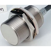
E2EM-X8C1 2M Omron, E2EM-X8C1 2M Datasheet

E2EM-X8C1 2M
Specifications of E2EM-X8C1 2M
Related parts for E2EM-X8C1 2M
E2EM-X8C1 2M Summary of contents
Page 1
... Note: Models with NPN NC output configurations are also available for all of the above models. NO E2EM-X4X1 2M * E2EM-X8X1 2M * E2EM-X15X1 2M * E2EM-X16MX1 E2EM-X30MX1 2M Output configuration: NPN NO E2EM-X2C1 2M E2EM-X4C1 2M E2EM-X8C1 2M E2EM-X15C1 2M Output configuration NPN NO CSM_E2EM_DS_E_3_1 Model NC E2EM-X4X2 2M E2EM-X8X2 2M E2EM-X15X2 2M E2EM-X16MX2 2M E2EM-X30MX2 2M Model Output configuration: NPN NC E2EM-X2C2 2M ...
Page 2
... XS2F-D421-GC0 XS2F-D421-G80-A XS2F-D422-DC0-A L-shape 2 m XS2F-D422-D80-A XS2F-D422-GC0 XS2F-D422-G80-A Note: Refer to Introduction to Sensor I/O Connectors for details. Use the XS2F-D42@-@CO-A for the E2EM-X@X1-M1J. (Terminal (+V), Terminal V)) Ratings and Specifications E2EM-X@X@ DC 2-Wire Models Size M12 Shielded Shielded Item Model E2EM-X4X ±10% Sensing distance Set distance * ...
Page 3
... E2EM-X@C@ DC 3-Wire Models Size M8 Shielded Shielded Item Model E2EM-X2C@(-M1 ±10% Sensing distance Set distance 0 to 1.6 mm Differential travel 10% max. of sensing distance Detectable object Ferrous metal (The sensing distance decreases with non-ferrous metal. Refer to Engineering Data on page 4.) Iron, 8 × 8 × Standard sensing object Response frequency *1 1 ...
Page 4
... Side length of sensing object: d (mm) E2EM-X16MX × Iron 12 Stainless steel (SUS304) 8 Brass Copper Aluminum Side length of sensing object: d (mm) E2EM E2EM-X@ E2EM-X15C 14 12 E2EM-X8C 10 8 E2EM-X4C 6 Y E2EM-X2C −20 −15 −10 − Distance Y (mm) E2EM-X8@@(-M1 × Iron 6 Stainless steel (SUS304) 4 Brass ...
Page 5
... I/O Circuit Diagrams E2EM-X@X@ DC 2-Wire Models Operation mode Model Non-sensing Sensing object E2EM-X4X1 E2EM-X8X1 NO E2EM-X15X1 E2EM-X16MX1 E2EM-X30MX1 Sensing object E2EM-X4X2 E2EM-X8X2 NC E2EM-X15X2 E2EM-X16MX2 E2EM-X30MX2 E2EM-X@C@(-M1) DC 3-Wire Models Operation Output specifi- Model mode cations E2EM-X2C1(-M1) E2EM-X4C@1-M1) NO E2EM-X8C1(-M1) E2EM-X15C1(-M1) NPN Open-collector output ...
Page 6
... V − )/ Example In this example, the above conditions are checked when the PLC Unit is the C200H-ID212, the Proximity Sensor is the E2EM-X8X1, and the power supply voltage (14.4 V) ≤ V (20.4 V) − 15 (1.3 mA) ≥ (0.8 mA): OFF leak (20.4 V) − − ...
Page 7
... Tolerance class IT16 applies to dimensions in this data sheet unless otherwise specified. Mounting Hole Dimensions Dimensions F (mm) F E2EM-X4@@ 21 dia. 17 M12 × E2EM-X15@@ 42 dia E2EM Part A Part B Dimension Torque Torque (mm N·m 12 N·m 30 N·m 70 N·m 180 N·m (Unit: mm) M8 M12 M18 +0.5 +0 ...
Page 8
... Standard length Two clamping nuts 2. X1 Models: Operation indicator (red), Setting indicator (green) Toothed washer X2 Models: Operation indicator (red) Mounting Hole Dimensions Dimensions F (mm) F E2EM-X4C@-M1 21 dia. 17 M12 × 1 E2EM-X15C@-M1 42 dia. 36 M12 × 1 Indicator* E2EM 2 , Insulator 2 , Insulator M8 M12 M18 M30 +0.5 +0 ...
Page 9
... Please read and understand this catalog before purchasing the products. Please consult your OMRON representative if you have any questions or comments. WARRANTY OMRON's exclusive warranty is that the products are free from defects in materials and workmanship for a period of one year (or other period if specified) from date of sale by OMRON. OMRON MAKES NO WARRANTY OR REPRESENTATION, EXPRESS OR IMPLIED, REGARDING NON-INFRINGEMENT, MERCHANTABILITY, OR FITNESS FOR PARTICULAR PURPOSE OF THE PRODUCTS ...


