STBVP6 BANNER ENGINEERING, STBVP6 Datasheet - Page 5
STBVP6
Manufacturer Part Number
STBVP6
Description
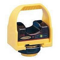
Photoelectric Touch Buttons
Manufacturer
BANNER ENGINEERING
Specifications of STBVP6
Output Current
150mA
Supply Voltage Range Dc
10V To 30V
Function
Proximity
Primary Type
Photoelectric
Technology
Photoelectric
Accessories Available
Cordsets, Field Covers and Brackets
Lead Free Status / Rohs Status
RoHS Exempt Product


The following example illustrates the
use of the formula to calculate
separation distance for a part-
revolution clutch machine. This
example uses 0.50 seconds as a typical
value for T s and 0.025 seconds for T r
and T h :
In this example, both hand controls
must be located no closer than 35"
from the nearest hazard point.
Hand controls must be mounted a safe
distance from moving machine parts, as
determined by OSHA Regulation CFR
1910.217 (c) (3) (vii) and (viii). It must not
be possible for the operator or other non-
qualified persons to relocate them. Failure
to establish and maintain the required
safety distance could result in serious
injury or death.
Example Separation Distance (D s )
K = 63" per second,
T s = 0.50 seconds
T r = 0.025 seconds
T h = 0.025 seconds
D s = K x (T s + T r + T h )
!
= 63" (0.50 + 0.025 + 0.025)
= 35"
Banner Engineering Corp.
www.bannerengineering.com • Tel: 763.544.3164
stop-time measuring device)
Calculation
WARNING ...
Location of Touch
Button Controls
(measured by a
•
Minneapolis, U.S.A.
STB Series Self-Checking Optical Touch Buttons
Separation Distance
Both hand controls must be located far enough away from the nearest hazard point that
the operator cannot reach the hazard with a hand or other body part before the hazardous
motion ceases (ANSI B11.19, 4.2.4.3.2). This is the “separation distance,” and may be
calculated as follows [see OSHA CFR 1910.217 (c) (3) (vii) & (viii)].
For Part-Revolution Clutch Machinery
Where the machine and its controls allow the machine to stop motion during the
hazardous portion of the machine cycle, use the following formula:
For Full-Revolution Clutch Machinery
Where the machine and its controls are designed to complete a full machine cycle,
once activated, use the following formula:
For both formulas:
NOTES:
1)
2)
3)
D s = the separation distance in inches,
K
T s = the stop time (in seconds) of the machine, measured from the application
T r = the response time of the Two-Hand-Control safety module as measured
T h = the response time of the slowest hand control (from the time when a hand
T m = the maximum time (in seconds) the machine takes to cease all motion after
The OSHA-recommended hand speed constant K has been determined by various studies, and although
these studies indicate speeds of 63"/sec to over 100"/sec, they are not conclusive determinations. The
employer should consider all factors, including the physical ability of the operator, when determining
the value of K to be used.
T s is usually measured by a stop-time measuring device. If the specified machine stop time is used,
add at least 20% as a safety factor to account for brake system deterioration. If the stop-time of the two
redundant machine control elements is unequal, the slower of the two times must be used for
calculating the separation distance.
T h is usually insignificant for purely mechanical switches. However, T h should be considered for
separation distance calculation when using electronic or electromechanical (i.e. powered) hand controls.
= 63" per second (the hand speed constant currently accepted by OSHA; see
NOTE 1, below),
of the “stop” signal to the final ceasing of all motion, including stop times
of all relevant control elements, and measured at maximum machine
velocity (see NOTE 2, below),
from the time either hand disengages a hand control
disengages that control until the switch opens; see NOTE 3, below)
it has been tripped. For full-revolution clutch presses with only one
engaging point, T m is equal to the time necessary for one and one-half
revolutions of the crankshaft. For full-revolution clutch presses with more
than one engaging point, T m is calculated as follows:
T m = (
N = number of clutch engaging points per revolution
T cy = time (in seconds) necessary to complete one revolution of the crankshaft
1
where:
/
2
+
1
/
N
) x T cy
D s = K x (T s + T r + T h )
D s = K x (T m + T r + T h )
page
5
Related parts for STBVP6
Image
Part Number
Description
Manufacturer
Datasheet
Request
R

Part Number:
Description:
Photoelectric Sensor
Manufacturer:
BANNER ENGINEERING
Datasheet:

Part Number:
Description:
Photoelectric Sensor
Manufacturer:
BANNER ENGINEERING
Datasheet:

Part Number:
Description:
LEDIR70XD4-XM-81039 MAX INTENS STROBE ONLY NO BANNER MARKS
Manufacturer:
BANNER ENGINEERING
Part Number:
Description:
M18SP6DL-72225 LABELED MOELLER NO BANNER MARKINGS BULK PACK
Manufacturer:
BANNER ENGINEERING
Part Number:
Description:
M18SP6DLQ-72226 LABLED MOELLER NO BANNER MARKINGS BULK PACK
Manufacturer:
BANNER ENGINEERING
Part Number:
Description:
M18SP6L-72223 LABELED MOELLER NO BANNER MARKINGS BULK PACK
Manufacturer:
BANNER ENGINEERING
Part Number:
Description:
M18SP6LQ-72224 LABELED MOELLER NO BANNER MARKINGS BULK PACK
Manufacturer:
BANNER ENGINEERING
Part Number:
Description:
P4D1-77908 P4 DRIVER GENERIC NO BANNER MARKINGS RESALE TO CUSTOMER
Manufacturer:
BANNER ENGINEERING
Part Number:
Description:
Photoelectric Sensor
Manufacturer:
BANNER ENGINEERING
Datasheet:

Part Number:
Description:
Programmable Indicator Light
Manufacturer:
BANNER ENGINEERING
Datasheet:
Part Number:
Description:
INDICATOR LED PANEL 50MM GRN/RED/YEL 30V
Manufacturer:
BANNER ENGINEERING
Datasheet:
Part Number:
Description:
Programmable Indicator Light
Manufacturer:
BANNER ENGINEERING
Datasheet: