PM4HA-H-24VS PANASONIC EW, PM4HA-H-24VS Datasheet - Page 5
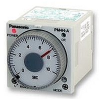
PM4HA-H-24VS
Manufacturer Part Number
PM4HA-H-24VS
Description
TIMER, MULTIFUNCTION, SCREW, 24VDC
Manufacturer
PANASONIC EW
Datasheet
1.PM4HA-H-24VS.pdf
(14 pages)
Specifications of PM4HA-H-24VS
Contact Configuration
DPDT
Nom Input Voltage
24V
Delay Time Range
1s To 500h
Adjustment Type
Knob
Relay Mounting
Panel
Svhc
No SVHC (15-Dec-2010)
Coil Voltage Vac Nom
24V
Coil Voltage Vdc
RoHS Compliant


Note: Keep 0.1s or more for power off time.
OPERATION MODE
PM4H-S
PM4H-M
Note: Keep 0.1s or more for power off time. PM4H-M timers do not have each input which is signal, reset and stop.
16
ON/OFF-delay (2)
Power ON-flicker
Power One-cycle
Operation mode
Operation mode
Power ON-delay
Operation mode
Power ON-delay
Power One-shot
Power Flicker
Differential
One-cycle
One-shot
Keep 0.05s or more for signal, stop, reset input time.
Pulse
Pulse
OF2
ON
OS
OC
OS
OC
FL
FO
Turn the operation selector to
Power is applied continuously. When a start signal is applied, the out-
put contacts change state immediately and time cycle begins. When
the time delay is completed, the output contacts return to their normal
state. The contacts will return to normal state when a reset signal is
applied or power is removed.
(Note: When a stop signal is applied during timing operation, the time
cycle stops. When a stop signal is removed, the time cycle begins.)
Turn the operation selector to
Power is applied continuously.
When a start signal is applied, the time cycle begins but output con-
tacts remain in their normal state. The output contacts change state
after time delay is completed. When the start signal is removed the
time cycle begins. The output contacts return to their normal state
after time delay is completed. The start signal is applied or start sig-
nal is removed while timing operation, the output contacts change
state and time cycle begins at this point.
The contacts will return to their normal state when a reset signal is
applied or power is removed.
(Note: When a stop signal is applied during timing operation, the time
cycle stops. When a stop signal is removed, the time cycle begins.)
Turn the operation selector to
Power is applied continuously.
When a start signal is applied, the time cycle begins but the output
contacts remain in their normal state. The output contacts change
state for 0.8s after time delay is completed.
Reset will occur when a reset signal is applied or power is removed.
(Note: When a stop signal is applied during timing operation, the time
cycle stops. When a stop signal is removed, the time cycle begins.)
When power is applied continuously, the time cycle begins. The out-
put contacts change state after the time delay is completed.
Power ON-delay
When power is applied continuously, the output contacts change
state.
Reset will occur when power is removed.
PM4H-M timers does not have each input which is signal, reset and
stop.
(As for other operation mode, refer to the operation mode of PM4H-
A.)
Operation
Operation
Operation
OS
OF2
OC
.
.
.
02/2003
Power ON-delay
Power supply
Time out (N.O. contact)
Instantaneous contact (N.O. contact)
OP. LED
POWER LED
Power supply
Time out (N.O. contact)
OP. LED
POWER LED
Power supply
Operation signal
Reset
Stop
Time out (N.O. contact)
OP. LED
POWER LED
Power supply
Operation signal
Reset
Stop
Time out (N.O. contact)
OP. LED
POWER LED
Power supply
Operation signal
Reset
Stop
Time out (N.O. contact)
OP. LED
POWER LED
One pulse time (t): Approx. 0.8s
Note:
Note:
Note:
–
–
–
–
–
–
–
–
–
ON
ON
ON
ON
ON
ON
ON
Time chart
Time chart
Time chart
T
LED lighting or No LED lighting
LED lighting or No LED lighting
T
T
LED lighting or No LED lighting
OFF
OFF
ON
t
ON
T: Setting time
ON
ON
ON
OFF
ON
LED lighting
ON
T
T
T
T
OFF
t
1
ON
PM4H-A/S/M
ON
ON
OFF
ON
t
1
OFF
t
t
1
2
ON
ON
OFF
OFF
OFF
t
2
OFF
t
OFF
OFF
OFF
OFF
OFF
2
ON
ON
LED flickering
t
t
a
OFF
ON
ON
OFF
t
t
b
a
t
a
OFF
ON
ON
OFF
OFF
ON
OFF
OFF
OFF
OFF
Restart
OFF
OFF
OFF
Related parts for PM4HA-H-24VS
Image
Part Number
Description
Manufacturer
Datasheet
Request
R

Part Number:
Description:
Analog Timer - PM4HA, Multi-function, DIN48, 8 Modes, Screw, 1 Sec - 500 Hr., 2 Form C, 100-240V AC
Manufacturer:
PANASONIC EW


Part Number:
Description:
TIMER RELAY ANALOG 24VAC/DC 11P
Manufacturer:
Panasonic Electric Works
Datasheet:
Part Number:
Description:
TIMER ANALOG MULTI 12VDC SCREW
Manufacturer:
Panasonic Electric Works
Datasheet:
Part Number:
Description:
TIMER RELAY ANALOG 24VAC/DC SCRW
Manufacturer:
Panasonic Electric Works
Datasheet:
Part Number:
Description:
TIMER RELAY ANALOG MULT 240VAC
Manufacturer:
Panasonic Electric Works
Datasheet:
Part Number:
Description:
TIMER ANALOG MULTI 12VDC 11PIN
Manufacturer:
Panasonic Electric Works
Datasheet:
Part Number:
Description:
TIMER RELAY ANALOG 240VAC SCREW
Manufacturer:
Panasonic Electric Works
Datasheet:

Part Number:
Description:
Manufacturer:
Panasonic Electric Works
Datasheet:

Part Number:
Description:
SIGNAL RELAY, DPDT, 5VDC, 2A, PC BOARD
Manufacturer:
PANASONIC EW
Datasheet:


Part Number:
Description:
PHOTOMOS RELAY, 60VDC, 400mA
Manufacturer:
PANASONIC EW
Datasheet:

Part Number:
Description:
PHOTOMOS RELAY, 400V, 150mA
Manufacturer:
PANASONIC EW
Datasheet: