PM4HA-H-24VS PANASONIC EW, PM4HA-H-24VS Datasheet - Page 14
PM4HA-H-24VS
Manufacturer Part Number
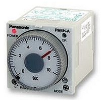
PM4HA-H-24VS
Description
TIMER, MULTIFUNCTION, SCREW, 24VDC
Manufacturer
PANASONIC EW
Datasheet
1.PM4HA-H-24VS.pdf
(14 pages)
Specifications of PM4HA-H-24VS
Contact Configuration
DPDT
Nom Input Voltage
24V
Delay Time Range
1s To 500h
Adjustment Type
Knob
Relay Mounting
Panel
Svhc
No SVHC (15-Dec-2010)
Coil Voltage Vac Nom
24V
Coil Voltage Vdc
RoHS Compliant


Notes for PM4H series
2) Connections of non-contact input
(open-collector)
Apply the open-collector connection. The
characteristics of the transistor used
must be V
more, and I
the input impedance must be 1kΩ or
less, and the residual voltage must be
0.6V or less.
3) Voltage input
Even if the open collector is not used,
input is also possible from the non-con-
tact circuit of 6 to 30V DC. In this case,
the signal input is turned on when the
signal is turned from H to L.
The residual voltage must be 0.6V or
less when Q is on. On the AC type, an
insulated transformer is required as the
power supply for the photoelectric sen-
sor, etc. (power supply for the input
devices).
Note: Keep the minimum input signal time of
each signal to 0.05s or more.
4. Power off time
Keep 0.1s (-A, -S, -M type), 0.5s (-SD/
SDM type), 0.3s (-W type) or more for
the power off time after time cycle is
completed.
Internal circuit
with photoelectric
sensor, etc.
CEO
CBO
=10V or more, I
=6µA or less. Additionally,
Q
1mA
(The signal input
is turned on at
L level.)
C
=10mA or
[Example of
signal input]
5. Cautions [Common]
1. Prevent using the timer in such places
where flammable or corrosive gas is
generated, a lot of dust exists, oil is
splashed or considerable shock and
vibration occur.
2. Since the main body cover is made of
polycarbonate resin, prevent contact with
organic solvents such as methyl alcohol,
benzine and thinner, or strong alkali
materials such as ammonia and caustic
soda.
3. External surge protection may be
required if the following values are
exceeded. Otherwise, the internal circuit
will be damaged.
Operation voltage
Surge wave form [±(1.2×50)µs single
polarity full wave voltage]
12V DC, 24V DC
100 to 240V AC
100 to 120V AC
200 to 240V AC
48 to 125V DC
100
24V AC/DC
90
50
30
0
24V AC
0
02/2003
1.2
Time
Crest value
(µs)
Surge voltage
50
4,000V
500V
4. For connecting and disconnecting
operating voltage to the timer, a circuit
should be used to prevent the flow of
leakage current. For example, a circuit
for contact protection as shown in Fig. A
will permit leakage current to flow
through R and C, causing erroneous
operation of the timer. Instead, the circuit
shown in Fig. B should be used.
5. In order to maintain the characteristics
of the timer, long continuous current flow
through the timer, causing generation of
heat internally should be avoided
because of the degradation it can cause.
For such long continuous operation, the
circuit shown below should be used.
Power
supply
R: contacts of
relay
No good
Leak current
(Fig. A)
R
R
C
T
R
R Relay
Power
supply
T
(Fig. B)
Good
T Time
R
R
C
T
27
Related parts for PM4HA-H-24VS
Image
Part Number
Description
Manufacturer
Datasheet
Request
R

Part Number:
Description:
Analog Timer - PM4HA, Multi-function, DIN48, 8 Modes, Screw, 1 Sec - 500 Hr., 2 Form C, 100-240V AC
Manufacturer:
PANASONIC EW


Part Number:
Description:
TIMER RELAY ANALOG 24VAC/DC 11P
Manufacturer:
Panasonic Electric Works
Datasheet:
Part Number:
Description:
TIMER ANALOG MULTI 12VDC SCREW
Manufacturer:
Panasonic Electric Works
Datasheet:
Part Number:
Description:
TIMER RELAY ANALOG 24VAC/DC SCRW
Manufacturer:
Panasonic Electric Works
Datasheet:
Part Number:
Description:
TIMER RELAY ANALOG MULT 240VAC
Manufacturer:
Panasonic Electric Works
Datasheet:
Part Number:
Description:
TIMER ANALOG MULTI 12VDC 11PIN
Manufacturer:
Panasonic Electric Works
Datasheet:
Part Number:
Description:
TIMER RELAY ANALOG 240VAC SCREW
Manufacturer:
Panasonic Electric Works
Datasheet:

Part Number:
Description:
Manufacturer:
Panasonic Electric Works
Datasheet:

Part Number:
Description:
SIGNAL RELAY, DPDT, 5VDC, 2A, PC BOARD
Manufacturer:
PANASONIC EW
Datasheet:


Part Number:
Description:
PHOTOMOS RELAY, 60VDC, 400mA
Manufacturer:
PANASONIC EW
Datasheet:

Part Number:
Description:
PHOTOMOS RELAY, 400V, 150mA
Manufacturer:
PANASONIC EW
Datasheet: