CES-A-BBA EUCHNER, CES-A-BBA Datasheet - Page 14
CES-A-BBA
Manufacturer Part Number
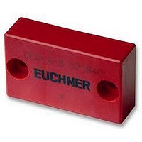
CES-A-BBA
Description
ACTUATOR
Manufacturer
EUCHNER
Datasheet
1.CES-A-BBA.pdf
(71 pages)
Specifications of CES-A-BBA
External Depth
40.5mm
External Length / Height
131mm
Operating Temperature Max
55°C
Operating Temperature Min
-0°C


Non-Contact Safety Switches CES/CEM
Evaluation unit CES-A-AEA...
Functional description
The Coded Electronic Safety switch CES comprises three
components:
Based on the concept of the safety switch CES-A-ABA..., the
evaluation units described in this chapter have the option of
connecting 1...2 or 1...4 read heads. As a result, up to four safety
guards can be monitored. The evaluation unit also has connection
terminals for a start button and for the feedback loop for monitoring
power contactors. The start button and the feedback loop are
monitored for short-circuits.
The following settings can be made optionally using DIP switches
on the evaluation unit:
The configuration of the entire system can be changed as often
as required using a "teach-in operation". After appropriate
preparations (fitting a jumper to the evaluation unit), a new actuator
can also be taught-in as often as required in service.
The non-contact safety switch CES-A-AEA... has a relatively large
operating distance of 15 mm. Compared with mechanical safety
switches, the assembly of the unit is much easier and the need
for precision in the door rails is also reduced considerably.
Therefore the assembly and maintenance costs are much lower.
The two-core connection cable to the evaluation unit is hard-wired
to the read head or can be plugged in using a round M8 plug
connector. In this way, the wiring work is reduced to an absolute
minimum.
The read heads are fastened to the fixed part of the safety guard
and are each connected to the evaluation unit via a two-core screened
cable. The actuator fastened to the movable part of the safety guard
is moved towards the read head by closing the door. When the
switch-on distance is reached, power is supplied to the actuator by
the inductive read head and data can be transferred.
The bit pattern read is compared with the code saved in the evaluation
unit. If the data match, the door monitoring output O1...O2 or O1...O4
(semiconductor output) on the related read head is set HIGH. If all
data for all read heads activated match, the safety outputs (relay
outputs) are then enabled. The OUT LED illuminates.
Due to the combination of dynamic polling of the actuators and
the redundant, diverse design of the safety electronics with the
two safety outputs, the evaluation unit will enter the safe state
with every conceivable fault.
14
Housing for DIN rail mounting, IP 20
Relay output
2 or 4 read heads can be connected
Coded actuator
Read head
Evaluation unit
Number of read heads 1...2 or 1...4
Manual or automatic start
Operation with or without feedback loop
Subject to technical modifications; no responsibility is accepted for the accuracy of this information.
When a safety guard is opened, the safety outputs switch off the
safety circuit and the OUT LED goes out. The state of the safety
outputs is monitored internally by positively driven NC contacts
(relay output). Independent of the switching state of the safety circuit,
the position of all safety doors can be polled via the outputs O1...O2
or O1...O4.
If an internal fault occurs in the evaluation unit, the safety circuit is
switched off, the diagnostic output (DIA) is set HIGH and the DIA
LED illuminates red.
The start button is also monitored. This is achieved by evaluating
the falling edge of the start signal. In this way it is not possible for
a signal continuously present on the input of the evaluation unit
(e.g. stuck button contact) to result in the automatic start of the
system.
The evaluation unit provides the option of monitoring power
contactors connected in series.
The evaluation unit can only be started with the feedback loop
closed. A welded contactor contact in the release path will thus
be detected when a start request is made.
The safety contacts on the new evaluation unit can switch switching
currents from 1 mA to 6 A. Since small currents can be switched,
the user has the option of connecting the safety switch CES directly
to a safe control system. Safe control systems will become
increasingly important as technology progresses.
With a switching capacity of DC 24 V / 6 A or AC 230 V / 1.5 A,
the evaluation unit can be connected directly to the majority of
power contactors, without further coupling modules.
With its new safety switch CES, EUCHNER has introduced an
integrated solution on the market. With a single system, the user
can realize such applications as the monitoring of safety guards,
wiring, evaluation and even the monitoring of externally connected
devices. The user thus achieves maximum safety at a reasonable
cost without the need for further equipment, e.g. emergency-stop
switchgear.
Due to the internal design of the device and the monitoring facility
for the external connected devices, the non-contact safety switch
CES-A-AEA... can be used for the highest safety requirements of
safety category 4 according to EN 954-1 with approval from BG
and SIBE Switzerland.
Related parts for CES-A-BBA
Image
Part Number
Description
Manufacturer
Datasheet
Request
R

Part Number:
Description:
ACTUATOR
Manufacturer:
EUCHNER
Datasheet:

Part Number:
Description:
ACTUATOR
Manufacturer:
EUCHNER
Datasheet:

Part Number:
Description:
ACTUATOR
Manufacturer:
EUCHNER
Datasheet:

Part Number:
Description:
JOYSTICK SWITCH
Manufacturer:
EUCHNER
Datasheet:

Part Number:
Description:
JOYSTICK SWITCH
Manufacturer:
EUCHNER
Datasheet:

Part Number:
Description:
JOYSTICK SWITCH
Manufacturer:
EUCHNER
Datasheet:

Part Number:
Description:
JOYSTICK SWITCH
Manufacturer:
EUCHNER
Datasheet:

Part Number:
Description:
JOYSTICK SWITCH
Manufacturer:
EUCHNER
Datasheet:


Part Number:
Description:
LIMIT SWITCH, SINGLE
Manufacturer:
EUCHNER
Datasheet:

Part Number:
Description:
SAFETY SWITCH
Manufacturer:
EUCHNER
Datasheet:

Part Number:
Description:
SAFETY SWITCH
Manufacturer:
EUCHNER
Datasheet:

Part Number:
Description:
SAFETY SWITCH
Manufacturer:
EUCHNER
Datasheet:

Part Number:
Description:
SAFETY SWITCH
Manufacturer:
EUCHNER
Datasheet:

Part Number:
Description:
CONN RCPT 8POS .100" SNGL TIN
Manufacturer:
Samtec Inc
Datasheet: