WKT 1234D EUCHNER, WKT 1234D Datasheet
WKT 1234D
Specifications of WKT 1234D


Related parts for WKT 1234D


WKT 1234D Summary of contents
Page 1
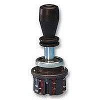
... Joystick Switches More than safety. ...
Page 2
... EUCHNER products are sold through a world-wide sales network of compe- tent partners. With our closeness to the customer and the guarantee of reliable solutions throughout the globe, we enjoy the confidence of cus- tomers all over the world ...
Page 3
... Joystick switches Application Design and function Advantages/features Series Series WK... Series WE... Series KB... Series KF... Series KE... Series KC... Series KP... Universal Power Supply Unit P1/P2 for series KP joysticks Housing HBL Housing HBE Front plates for housing HBL and HBE Technical status 09-03/06 Table of contents Control panel installation to IEC 947-5-1 D30 ...
Page 4
... EUCHNER joysticks are used in the steel and construction industry, in machine tools, for transport and conveyor systems, in the system and mechanical engineering sectors and for warehousing, medical and studio technology. With the certification, the devices are approved for use in the ship-building industry ...
Page 5
... Joystick switches Models EUCHNER joystick switches are available in a number of different models: Series WK... (page 6) Series KF... (page 12) Series KP... (page 19) Subject to technical modifications; no responsibility is accepted for the accuracy of this information. Series WE... (page 8) Series KE... (page 14) Housing kits (from page 22) suitable for series WK, KB, KE and KF Series KB ...
Page 6
... Joystick switches Series WK... Control panel installation to IEC 947-5-1 D30 actuating directions with spring return operation or combined One changeover contact with tab connector 2.8 x 0.5 IEC 760 for each actuating direction Centre position switch Pushbutton in handle Dimension drawing Ordering code Series Actuating direction and switching behavior ...
Page 7
... Joystick switch series WK, actuating directions 1+3 stayput switch S, actuating directions 2+4 spring return switch T, Pushbutton D, centre position switch Z, Interlock V in centre position Joystick switch series WK, 8 switching elements as spring return switches, all-round actuation R Design Joystick switch series WK, 4 switching elements, 2 actuating directions (2 switching elements per actuating direction) * Diagonal actuation of 4 adjacent switching elements is on request ...
Page 8
... Joystick switches Series WE... Control panel installation at rear or with front plate actuating directions with stayput or spring return operation or combined One changeover contact with screw terminal for each actuating direction Centre position switch Pushbutton in handle Dimension drawing Ordering code Series Actuating direction and switching behavior ...
Page 9
... Joystick switch series WE, actuating directions 1+3 stayput switch S, actuating directions 2+4 spring return switch T, Pushbutton D, centre position switch Z, Interlock V in centre position Joystick switch series WE, 8 switching elements as spring return switches, all-round actuation R Design Joystick switch series WE, 4 switching elements, 2 actuating directions (2 switching elements per actuating direction) Subject to technical modifications ...
Page 10
... Joystick switches Series KB... Control panel installation to IEC 947-5-1 D30 actuating directions, 4 switching elements. With stayput or spring return operation or combined One changeover contact with tab connector 6.3 x 0.8 IEC 760 for each actuating direction Dimension drawing Ordering code Series Actuating direction and switching behavior ...
Page 11
... Joystick switches Technical data Parameters Housing material Switching lever material Degree of protection to IEC 529 on actuating side with bellows Mounting method Weight Mechanical life spring return switch stayput switch Ambient temperature with spring return switch Ambient temperature with stayput switch Max number of switching elements ...
Page 12
... Joystick switches Series KF... Control panel installation at rear actuating directions, 4 switching elements. With stayput or spring return operation or combined One changeover contact with screw terminal for each actuating direction Centre position switch Dimension drawing ∅ 72 ∅ 32 ∅ 20 22x1,5 Bellows Centre position switch Z (actuated in centre ...
Page 13
... Joystick switches Technical data Parameters Housing material Switching lever material Degree of protection to IEC 529 on actuating side with bellows Mounting method Weight Mechanical life Ambient temperature with spring return switch Ambient temperature with stayput switch Max. number of switching elements Connection type Contact elements ...
Page 14
... Joystick switches Series KE... Control panel installation to IEC 947-5-1 D22 actuating directions, 4 switching elements. With stayput or spring return operation or combined One changeover contact with tab connector 2.8 x 0.5 IEC 760 for each actuating direction Centre position switch Dimension drawing Interlock V Bellows Centre position switch Z ...
Page 15
... Joystick switches Technical data Parameters Housing material Switching lever material Degree of protection to IEC 529 on actuating side with bellows Mounting method Weight Mechanical life Ambient temperature with spring return switch Ambient temperature with stayput switch Max. number of switching elements Connection type Contact elements ...
Page 16
... Joystick switches Series KC... control panel installation at rear or with front plate actuating directions with switching positions for each actuating direction Switching positions as stayput or spring return operation in various combinations Centre position switch Pushbutton in handle Dimension drawing Main actuating directions and 4 16 Germanischer Lloyd Certificate no ...
Page 17
... Joystick switches Technical data Parameters Housing material Switching lever material Degree of protection to IEC 529 on actuating side with / without bellows Mounting method Weight Mechanical life Ambient temperature with spring return switch Ambient temperature with stayput switch Max. number of switching elements Connection type ...
Page 18
... Joystick switches Series KC... Switching behavior 1) G Stayput switch (switching lever latches in selected position) Spring return switch (switching lever returns to initial position) Ordering Switching position code Ordering code K C Series Connection type Tab connector 2.8 x 0.5 IEC 760 Screw terminal Main actuating direction 1 ...
Page 19
... Joystick switches Series KP... control panel installation at rear or with front plate Analog, proportional output signals Control variants with 1 and 2 axes or 2 axes simultaneously Centre position switch Pushbutton in handle Dimension drawing Subject to technical modifications; no responsibility is accepted for the accuracy of this information. 1) Panel cutout for assembly ...
Page 20
... Joystick switches Technical data Parameters Housing material Switching lever material Degree of protection to IEC 529 on actuating side with / without bellows Mounting method Weight Mechanical life Ambient temperature with spring return switch Ambient temperature with stayput switch Max. number of switching elements Connection type ...
Page 21
... Joystick switches Series KP... Pin assignment Connection Centre position switch Output Ordering code Series Control variants 1 axis 1 2 axes 2 2 axes simultaneously 3 End position Stayput switch S Spring return switch T Options Pushbutton D Bellows for panel mounting W Bellows for surface mounting X Interlock V Centre position switch ...
Page 22
... The universal power supply unit P1/P2 comprises 114 the unit P1UG4A018 (P1) for the supply of the EUCHNER series KP joystick. The unit P2RV3A24P (P2) is used as a switch amplifier for the connection of three inductive proximity switches or single hole fixing limit switches. In addition, it can also be used as a simple power supply ...
Page 23
... Joystick switches Housing HBL Dimension drawing A View A Magnetic clamp ∅ D ∅ D Note 2 versions for different cable glands Technical data Parameters Housing HBL Material Color Ambient temperature Degree of protection to EN 60529 Weight Ordering table Design Type designation Housing HBL, with magnetic clamp, hanging clip, fixing nut ...
Page 24
... Joystick switches Housing HBE Dimension drawing View A Hanging clip ∅ D ∅ D Notes 2 versions for different cable glands Technical data Parameters Housing HBE Material Color Ambient temperature Degree of protection to EN 60529 Weight Ordering table Design Type designation Housing HBE, with magnetic clamp, hanging clip, fixing nut ...
Page 25
... Joystick switches Front plates for housing HBL and HBE Dimension drawing Front plates HBL Flat seal Technical data Material front plate Material seal Ordering table Type designation Front plate for HBL housing, with seal Front plate for HBE housing, with seal Subject to technical modifications ...
Page 26
... Cheung Lee Industrial Building Fax +1 (5 19) 966-6160 9 Cheung Lee Street sales@iacnassociates.com HK-Chaiwan, Hong Kong Tel. +8 52/ China Fax +8 52/ EUCHNER Electric Shanghai Ltd. ieeclhk@netvigator.com No. 8 Workshop, Hi-Tech Zone N. 503 MeiNengDa Road Hungary Songjiang Industrial Zone EUCHNER Ges.mbH Shanghai Magyarországi Fióktelep Tel. +86 (0) 21 5774 7090 H-2045 Tö ...
Page 27
... offic He d offic d offic offic offic EUCHNER GmbH + Co. KG Kohlhammerstraße 16 D-70771 Leinfelden-Echterdingen Germany Tel. +49/7 11/75 97-0 Fax +49/7 11/ info@euchner.de www www euc www euc euc hner hner hner www www euc euchner hner om om More than safety. More than safety. More than safety. Mor than safety ...